HP Cluster Platform Interconnects v2010 Quadrics QsNetII Interconnect - Page 29
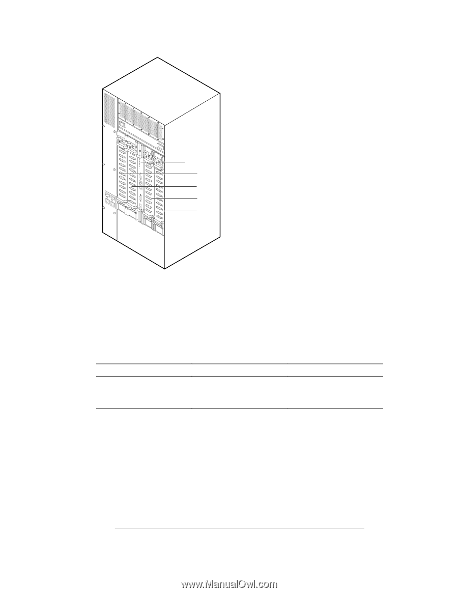
Interconnect, Rear View with Slot Numbering
 |
View all HP Cluster Platform Interconnects v2010 manuals
Add to My Manuals
Save this manual to your list of manuals |
Page 29 highlights
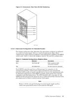
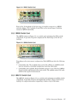
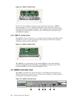
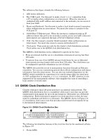
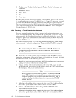
Figure 3-3: Interconnect, Rear View with Slot Numbering Slot 0 Slot 1 Fan A/CtrlA Slot 2 Slot 3 Fan A/CtrlA Slot 0 Slot 1 Slot 2 Slot 3 HPTC-0028 3.2.3.2 Interconnect Configuration for Federated Clusters For clusters with greater than 128 nodes, the interconnect enclosure is configured as a node-level interconnect (NLI) or a top-level interconnect (TLI). These configurations require different midplanes and combinations of QM501 and QM502 switch cards. Table 3-1 shows the midplane rules for TLI and NLI configurations. Table 3-1: Federated Configurations, Midplane Rules Level Midplane Description NLI 3X-CS5A0-AF Fully populated with connectors installed TLI 3X-CM5A0-AN No link connectors installed Each QM503 controller card has an Ethernet port for connection to the management network. If these ports remain unconnected, the management processes will be unable to report network state or errors to the management node. In federated configurations, both QM503 controller cards operate from separate redundant clock distribution boxes. Two RJ45 shielded cable connectors on each QM503 provide external clock inputs for use in a federated network. External clock port plugs must be fitted to unused external clock inputs. Note Failure to fit the external clock plugs to unused inputs might result in clock errors generated by noise on the internal clock signal. 128-Port Interconnect Modules 3-5
-
 1
1 -
2
-
3
-
4
-
5
-
6
-
7
-
8
-
9
-
10
-
11
-
12
-
13
-
14
-
15
-
16
-
17
-
18
-
19
-
20
-
21
-
22
-
23
-
 24
24 -
 25
25 -
 26
26 -
 27
27 -
 28
28 -
 29
29 -
 30
30 -
 31
31 -
 32
32 -
 33
33 -
 34
34 -
35
-
36
-
37
-
38
-
39
-
40
-
41
-
42
-
43
-
44
-
45
-
46
-
47
-
48
-
49
-
50
-
51
-
52
-
53
-
54
-
55
-
56
-
57
-
58
-
59
-
60
-
61
-
62
-
63
-
64
-
65
-
66
-
67
-
68
-
69
-
70
-
71
-
72
-
73
-
74
-
75
-
76
-
77
-
78
-
79
-
80
-
81
-
82
-
83
-
84
-
85
-
86
-
87
-
88
-
89
-
90
-
91
-
92
-
93
-
94
-
95
-
96
-
97
-
98
-
99
-
100
-
101
-
102
-
103
-
104
-
105
-
106
-
107
-
108
-
109
-
110
-
111
-
112
-
113
-
114
-
115
-
116
-
117
-
118
-
119
-
120
-
121
-
122
-
123
-
124
-
125
-
126
-
127
-
128
-
129
-
130
-
131
-
132
-
133
-
134
-
135
-
136
-
137
-
138
-
139
-
140
-
141
-
142
-
143
-
144
-
145
-
146
-
147
-
148
-
149
-
150
-
151
-
152
-
153
-
154
-
155
-
156
-
157
-
158
-
159
-
160
-
161
-
162
-
163
-
164
-
165
-
166
 |
 |