HP Cluster Platform Interconnects v2010 Quadrics QsNetII Interconnect - Page 71
Securing the Slides to the Interconnect Chassis, Caution
 |
View all HP Cluster Platform Interconnects v2010 manuals
Add to My Manuals
Save this manual to your list of manuals |
Page 71 highlights
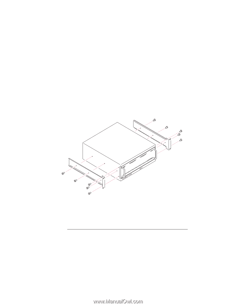
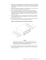
6. Fasten the two front tracks to the rack columns by using four screws (two in each column). Do not tighten the screws at this time. (No screw thread should show, but the screws should be loose enough to allow for minor adjustment of the track). 7. Adjust the position of the sliding cable management bracket and tighten all 4 M4 x 10 mm knurled-head bolts to secure it in place. 8. Temporarily insert the slide rails into the tracks and slide them all the way in until the flange is flush with the front rack columns. Observe the position of the holes in the flange for the four locking screws that secure the interconnect in the rack. Mark the rack column holes that align with the locking screw holes. 9. Remove the slides and insert a cage nut into the back of the rack column at each marked location. If you find it difficult to insert the cage nut, loosen the front track a little more. 10. Secure the slides to the sides of the interconnect chassis by using 5 M4 x 10 mm cross-head screws on each side, as shown in Figure 8-4. Figure 8-4: Securing the Slides to the Interconnect Chassis Caution Step 8 requires two persons to lift the interconnect into the rack. Remember that the tracks are not yet tightened securely to the rack columns, allowing for minor adjustment of location. 11. Lift and slide the chassis into the rack, ensuring that the slides lock into the track. Secure the slides to the rails by using four screws at the front rack columns as shown in . Maintenance of the 16/32-Port Interconnect 8-5
-
 1
1 -
2
-
3
-
4
-
5
-
6
-
7
-
8
-
9
-
10
-
11
-
12
-
13
-
14
-
15
-
16
-
17
-
18
-
19
-
20
-
21
-
22
-
23
-
24
-
25
-
26
-
27
-
28
-
29
-
30
-
31
-
32
-
33
-
34
-
35
-
36
-
37
-
38
-
39
-
40
-
41
-
42
-
43
-
44
-
45
-
46
-
47
-
48
-
49
-
50
-
51
-
52
-
53
-
54
-
55
-
56
-
57
-
58
-
59
-
60
-
61
-
62
-
63
-
64
-
65
-
 66
66 -
 67
67 -
 68
68 -
 69
69 -
 70
70 -
 71
71 -
 72
72 -
 73
73 -
 74
74 -
 75
75 -
 76
76 -
77
-
78
-
79
-
80
-
81
-
82
-
83
-
84
-
85
-
86
-
87
-
88
-
89
-
90
-
91
-
92
-
93
-
94
-
95
-
96
-
97
-
98
-
99
-
100
-
101
-
102
-
103
-
104
-
105
-
106
-
107
-
108
-
109
-
110
-
111
-
112
-
113
-
114
-
115
-
116
-
117
-
118
-
119
-
120
-
121
-
122
-
123
-
124
-
125
-
126
-
127
-
128
-
129
-
130
-
131
-
132
-
133
-
134
-
135
-
136
-
137
-
138
-
139
-
140
-
141
-
142
-
143
-
144
-
145
-
146
-
147
-
148
-
149
-
150
-
151
-
152
-
153
-
154
-
155
-
156
-
157
-
158
-
159
-
160
-
161
-
162
-
163
-
164
-
165
-
166
 |
 |