HP Cluster Platform Interconnects v2010 Quadrics QsNetII Interconnect - Page 91
Controller Card LEDs, 2.3 Power Supply Unit LEDs, 2.4 Clock Generator LEDs
 |
View all HP Cluster Platform Interconnects v2010 manuals
Add to My Manuals
Save this manual to your list of manuals |
Page 91 highlights
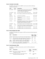
10.2.2 Controller Card LEDs The LEDs on the interconnect's QM503 control card provide the following diagnostic information: Label Pri Clk OK Color green Sec Clk OK B Clock Active Clk Error Federated green amber red green Redundant green Ctrl Run green Cntrl Error B Cntrl Active Fan Fail A Fan Fail B red amber red red Interpretation Diagnostic The input from the primary clock is good. This indicator applies only when the interconnect is part of a federated configuration. Error if OFF The input from the secondary clock is good. Error if OFF The secondary controller (slot A) clock is inactive. Error if ON A clock error is detected. Error if ON This interconnect is part of a federated configuration. True if ON This interconnect is part of a redundant configuration. True if ON This controller has booted and has a status of good. Error if OFF This indicator might take up to five minutes to illuminate after the controller is rebooted. The controller in slot A is not operating correctly. Error if OFF The controller in slot A is not operating correctly, Error if OFF and its error status LED (red) will be illuminated. The QM562 module in fan tray A has failed. Error if ON The QM562 module in fan tray B has failed. Error if ON 10.2.3 Power Supply Unit LEDs The LEDs in the QS5A power supply unit (PSU) provide the following diagnostic information: Label AC OK FAULT OVER TEMP DC OK Interpretation Good Error Status Status The alternating current (AC) power inlet supply indicator. Green Red PSU fault indicator. This might illuminate if the alternating OFF Red current (AC) power inlet supply or DC output indicator. The PSU temperature indicator. This might illuminate if OFF Red the PSU runs too hot, perhaps due to a fan problem. The DC power output indicator. This might illuminate if the DC voltage drops below a specified level. Green Amber 10.2.4 Clock Generator LEDs The LEDs in the QM580 clock generator provide the following diagnostic information: Label Interpretation PWR ON The AC power supply is working (power is applied to the clock). CLK In Ok This clock generator is in slave mode and its input from the master clock is OK. Good Status Green Error Status OFF Green N/A (status only) Using Component LEDs 10-5
-
 1
1 -
2
-
3
-
4
-
5
-
6
-
7
-
8
-
9
-
10
-
11
-
12
-
13
-
14
-
15
-
16
-
17
-
18
-
19
-
20
-
21
-
22
-
23
-
24
-
25
-
26
-
27
-
28
-
29
-
30
-
31
-
32
-
33
-
34
-
35
-
36
-
37
-
38
-
39
-
40
-
41
-
42
-
43
-
44
-
45
-
46
-
47
-
48
-
49
-
50
-
51
-
52
-
53
-
54
-
55
-
56
-
57
-
58
-
59
-
60
-
61
-
62
-
63
-
64
-
65
-
66
-
67
-
68
-
69
-
70
-
71
-
72
-
73
-
74
-
75
-
76
-
77
-
78
-
79
-
80
-
81
-
82
-
83
-
84
-
85
-
 86
86 -
 87
87 -
 88
88 -
 89
89 -
 90
90 -
 91
91 -
 92
92 -
 93
93 -
 94
94 -
 95
95 -
 96
96 -
97
-
98
-
99
-
100
-
101
-
102
-
103
-
104
-
105
-
106
-
107
-
108
-
109
-
110
-
111
-
112
-
113
-
114
-
115
-
116
-
117
-
118
-
119
-
120
-
121
-
122
-
123
-
124
-
125
-
126
-
127
-
128
-
129
-
130
-
131
-
132
-
133
-
134
-
135
-
136
-
137
-
138
-
139
-
140
-
141
-
142
-
143
-
144
-
145
-
146
-
147
-
148
-
149
-
150
-
151
-
152
-
153
-
154
-
155
-
156
-
157
-
158
-
159
-
160
-
161
-
162
-
163
-
164
-
165
-
166
 |
 |