HP Cluster Platform Interconnects v2010 Quadrics QsNetII Interconnect - Page 65
Typical Midplane kit Components
 |
View all HP Cluster Platform Interconnects v2010 manuals
Add to My Manuals
Save this manual to your list of manuals |
Page 65 highlights
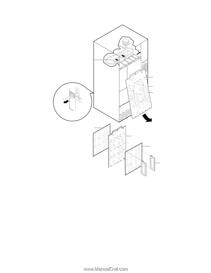
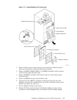
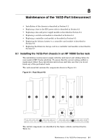
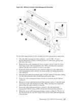
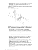
Figure 7-11: Typical Midplane kit Components Midplane Wiring Looms (2) Rear View PSU A PSU B Captive Fasteners (22) Original Midplane Midplane Handles (2) Switch Off and Remove Power Cords Rear Protective Cover Replacement Midplane Front Protective Cover Midplane Handles (2) HPTC-0032 2. Ensure that the power to the interconnect is turned off and that the power cables are disconnected. Label and disconnect all cables. 3. Remove all QM501, QM502, QM511C, and QM511L modules and set aside in a safe location using anti-static bags. 4. Remove all QM503 controller cards and set aside in a safe location using anti-static bags. 5. Remove all QM562 fan trays and all blank cards. 6. Disconnect the two QM573-x midplane wiring looms from the top of the midplane. If necessary, carefully remove one of the card guides to gain access. Position the cables out of the way. 7. Fit two midplane handles to the board. 8. Slacken off all the captive fasteners holding the midplane in place, being careful not to let the midplane slip out of position, thereby risking damage. Installation and Maintenance of the 128-Port Interconnect 7-17
-
 1
1 -
2
-
3
-
4
-
5
-
6
-
7
-
8
-
9
-
10
-
11
-
12
-
13
-
14
-
15
-
16
-
17
-
18
-
19
-
20
-
21
-
22
-
23
-
24
-
25
-
26
-
27
-
28
-
29
-
30
-
31
-
32
-
33
-
34
-
35
-
36
-
37
-
38
-
39
-
40
-
41
-
42
-
43
-
44
-
45
-
46
-
47
-
48
-
49
-
50
-
51
-
52
-
53
-
54
-
55
-
56
-
57
-
58
-
59
-
 60
60 -
 61
61 -
 62
62 -
 63
63 -
 64
64 -
 65
65 -
 66
66 -
 67
67 -
 68
68 -
 69
69 -
 70
70 -
71
-
72
-
73
-
74
-
75
-
76
-
77
-
78
-
79
-
80
-
81
-
82
-
83
-
84
-
85
-
86
-
87
-
88
-
89
-
90
-
91
-
92
-
93
-
94
-
95
-
96
-
97
-
98
-
99
-
100
-
101
-
102
-
103
-
104
-
105
-
106
-
107
-
108
-
109
-
110
-
111
-
112
-
113
-
114
-
115
-
116
-
117
-
118
-
119
-
120
-
121
-
122
-
123
-
124
-
125
-
126
-
127
-
128
-
129
-
130
-
131
-
132
-
133
-
134
-
135
-
136
-
137
-
138
-
139
-
140
-
141
-
142
-
143
-
144
-
145
-
146
-
147
-
148
-
149
-
150
-
151
-
152
-
153
-
154
-
155
-
156
-
157
-
158
-
159
-
160
-
161
-
162
-
163
-
164
-
165
-
166
 |
 |