HP Cluster Platform Interconnects v2010 Quadrics QsNetII Interconnect - Page 63
Disconnecting Link Cables, 6.3 Checking Link Cables, 6.4 Connecting the Interconnect to
 |
View all HP Cluster Platform Interconnects v2010 manuals
Add to My Manuals
Save this manual to your list of manuals |
Page 63 highlights
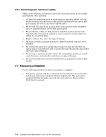
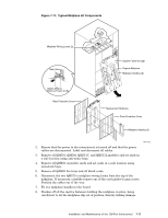
4. When all of the required cables are connected, fit a QM574 EMC shielded connector cover to all unused ports. 7.6.2 Disconnecting Link Cables Remove links as follows: 1. If you are replacing a bad link, route the replacement cable first. Note You might not want to go to the trouble of completely removing a bad cable unless it is to be returned for replacement. In this case, mark the cable as bad and route the new cable. 2. Halt the node or nodes to prevent them from crashing. 3. Remove the links a row at a time, starting at the top right. (This gives sufficient space to remove and replace each cable without damaging the connector pins). You can configure a link out of the network without the need to physically disconnect it by using the interconnect's management interface. 7.6.3 Checking Link Cables Each HD50 connector on the front panel of the interconnect switch card has a stack of three LEDs associated with it. Interpret the LEDs as follows: 1. The green LED is lit to indicate that the link is working. If the green LED is not lit after you connect the link cable, refer to the diagnostics section. 2. The yellow LED is lit to indicate that the link is active. 3. The red LED is lit to indicate that an error has occurred on the link. The red LED is normally lit after connecting a link to a node because the link is reset when the node boots. Such reset indications are cleared by software after the node has booted and the LED should cease to glow. If it persists, there is a problem with the link. 7.6.4 Connecting the Interconnect to the Control Network You must configure the internet with an IP address by using a local connection from a dumb terminal or a PC. When you have assigned an IP address to the controller, connect the interconnect to the control network using the Ethernet connection of the QM503 controller card. Warning The QM584 clock cables from the QM503 controller card to the QM580 clock distribution box and the Ethernet cable from the QM503 controller card to the control network are very similar; both types of cable are fitted with RJ45 connectors. When cabling the system, be sure to use the correct cables. Installation and Maintenance of the 128-Port Interconnect 7-15
-
 1
1 -
2
-
3
-
4
-
5
-
6
-
7
-
8
-
9
-
10
-
11
-
12
-
13
-
14
-
15
-
16
-
17
-
18
-
19
-
20
-
21
-
22
-
23
-
24
-
25
-
26
-
27
-
28
-
29
-
30
-
31
-
32
-
33
-
34
-
35
-
36
-
37
-
38
-
39
-
40
-
41
-
42
-
43
-
44
-
45
-
46
-
47
-
48
-
49
-
50
-
51
-
52
-
53
-
54
-
55
-
56
-
57
-
 58
58 -
 59
59 -
 60
60 -
 61
61 -
 62
62 -
 63
63 -
 64
64 -
 65
65 -
 66
66 -
 67
67 -
 68
68 -
69
-
70
-
71
-
72
-
73
-
74
-
75
-
76
-
77
-
78
-
79
-
80
-
81
-
82
-
83
-
84
-
85
-
86
-
87
-
88
-
89
-
90
-
91
-
92
-
93
-
94
-
95
-
96
-
97
-
98
-
99
-
100
-
101
-
102
-
103
-
104
-
105
-
106
-
107
-
108
-
109
-
110
-
111
-
112
-
113
-
114
-
115
-
116
-
117
-
118
-
119
-
120
-
121
-
122
-
123
-
124
-
125
-
126
-
127
-
128
-
129
-
130
-
131
-
132
-
133
-
134
-
135
-
136
-
137
-
138
-
139
-
140
-
141
-
142
-
143
-
144
-
145
-
146
-
147
-
148
-
149
-
150
-
151
-
152
-
153
-
154
-
155
-
156
-
157
-
158
-
159
-
160
-
161
-
162
-
163
-
164
-
165
-
166
 |
 |