HP Cluster Platform Interconnects v2010 Quadrics QsNetII Interconnect - Page 72
Replacing the Power Inlet Fuse
 |
View all HP Cluster Platform Interconnects v2010 manuals
Add to My Manuals
Save this manual to your list of manuals |
Page 72 highlights
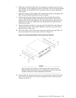
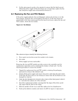
Figure 8-5: Installing the Chassis in the Rack Front of Rack 12. Tighten all the screws that secure the front and rear tracks Note The cable management assembly must support and align the cables and connectors with the Infiniband ports. As part of the cabling procedure, you might need to adjust the position of the cable management assembly so that it adequately supports the cables and also enables easy removal of a cable when required. The chassis is now ready for cabling. Use the cabling tables for your model of HP cluster platform to determine the origin node and destination port for each link, if the links are not already labeled. Each port has a numeric identifier (0-32) that forms part of the destination address of the link. (The address is a string that identifies the interconnect chassis, rail, and port). 8.2 Replacing the Power Inlet Fuse If the interconnect fails to power up, first inspect the fuse and replace it if necessary. Use the following procedure to 1. Remove power from the chassis by switching off the power switch and disconnecting the power cord at the IEC60320 appliance inlet. (Do not remove the power cord at the rack's power strip unless you label its location. 2. Remove the fuse cover, which is between the power switch and the inlet socket, as shown by callout 1 in Figure 4-1. 3. Discard the burned-out fuse and install the spare fuse that is stored inside the fuse cover. (Replace the spare fuse as soon as possible with a 20 mm x 5 mm slow-blow ceramic fuse of the same voltage and amperage values). 4. Replace the fuse cover and reconnect the power cord. 5. Power on the interconnect and ensure that the power LED is lit and that the fans are operating. 8-6 Maintenance of the 16/32-Port Interconnect
-
 1
1 -
2
-
3
-
4
-
5
-
6
-
7
-
8
-
9
-
10
-
11
-
12
-
13
-
14
-
15
-
16
-
17
-
18
-
19
-
20
-
21
-
22
-
23
-
24
-
25
-
26
-
27
-
28
-
29
-
30
-
31
-
32
-
33
-
34
-
35
-
36
-
37
-
38
-
39
-
40
-
41
-
42
-
43
-
44
-
45
-
46
-
47
-
48
-
49
-
50
-
51
-
52
-
53
-
54
-
55
-
56
-
57
-
58
-
59
-
60
-
61
-
62
-
63
-
64
-
65
-
66
-
 67
67 -
 68
68 -
 69
69 -
 70
70 -
 71
71 -
 72
72 -
 73
73 -
 74
74 -
 75
75 -
 76
76 -
 77
77 -
78
-
79
-
80
-
81
-
82
-
83
-
84
-
85
-
86
-
87
-
88
-
89
-
90
-
91
-
92
-
93
-
94
-
95
-
96
-
97
-
98
-
99
-
100
-
101
-
102
-
103
-
104
-
105
-
106
-
107
-
108
-
109
-
110
-
111
-
112
-
113
-
114
-
115
-
116
-
117
-
118
-
119
-
120
-
121
-
122
-
123
-
124
-
125
-
126
-
127
-
128
-
129
-
130
-
131
-
132
-
133
-
134
-
135
-
136
-
137
-
138
-
139
-
140
-
141
-
142
-
143
-
144
-
145
-
146
-
147
-
148
-
149
-
150
-
151
-
152
-
153
-
154
-
155
-
156
-
157
-
158
-
159
-
160
-
161
-
162
-
163
-
164
-
165
-
166
 |
 |
