HP Cluster Platform Interconnects v2010 Quadrics QsNetII Interconnect - Page 74
Replacing the Switch Card Module, 5 Replacing the Controller Module
 |
View all HP Cluster Platform Interconnects v2010 manuals
Add to My Manuals
Save this manual to your list of manuals |
Page 74 highlights
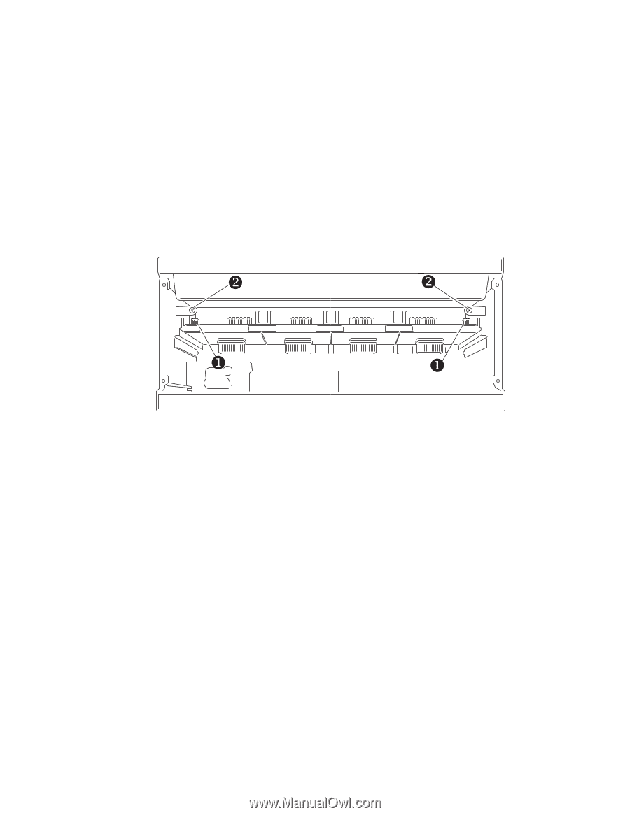
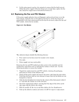
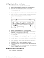
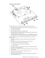
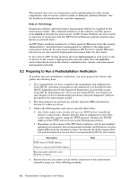
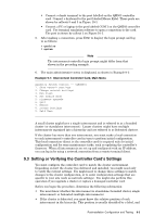
8.4 Replacing the Switch Card Module Use the following procedure to replace the switch card module: 1. Unpack the replacement module, retaining all the packaging materials. 2. Switch off the power and disconnect the power cord at the inlet. 3. Disconnect all the cables and remove the interconnect chassis from the rack as described in Section 4.2.2. 4. Remove the Fan and PSU module as described in Section 8.3 and put it aside in a safe location. 5. Remove the two screws (, callout 2) that secure the module's stiffener bar to the chassis, and disconnect the two power cables (, callout 1). Figure 8-7: Switch Card Module Y Y X X 6. Disconnect the ribbon data cable from the controller module. 7. Undo the module's four captive screws shown in Figure 4-1, callout 8 and carefully slide the switch module out of the chassis. 8. Remove the ribbon cable from the defective module and connect it to the replacement module. 9. Insert the replacement module, ensuring that the edges of the lower metal tray align with the slots in the casing. Slide the module all the way in. 10. Secure the four screws on the rear panel and the two screws on the stiffener bar (, callout 2). 11. Connect the two power cables (, callout 1) and connect the ribbon cable to the controller module. 12. Reinstall the fan and PSU Module as described in Section 8.3. 13. Replace the chassis in the rack and reconnect all the link cables as described in Section 4.2.1. 14. Pack the defective module using the packaging from the replacement module and return it to HP for repair or replacement. 8.5 Replacing the Controller Module Figure 8-8 shows the controller module. 8-8 Maintenance of the 16/32-Port Interconnect
-
 1
1 -
2
-
3
-
4
-
5
-
6
-
7
-
8
-
9
-
10
-
11
-
12
-
13
-
14
-
15
-
16
-
17
-
18
-
19
-
20
-
21
-
22
-
23
-
24
-
25
-
26
-
27
-
28
-
29
-
30
-
31
-
32
-
33
-
34
-
35
-
36
-
37
-
38
-
39
-
40
-
41
-
42
-
43
-
44
-
45
-
46
-
47
-
48
-
49
-
50
-
51
-
52
-
53
-
54
-
55
-
56
-
57
-
58
-
59
-
60
-
61
-
62
-
63
-
64
-
65
-
66
-
67
-
68
-
 69
69 -
 70
70 -
 71
71 -
 72
72 -
 73
73 -
 74
74 -
 75
75 -
 76
76 -
 77
77 -
 78
78 -
 79
79 -
80
-
81
-
82
-
83
-
84
-
85
-
86
-
87
-
88
-
89
-
90
-
91
-
92
-
93
-
94
-
95
-
96
-
97
-
98
-
99
-
100
-
101
-
102
-
103
-
104
-
105
-
106
-
107
-
108
-
109
-
110
-
111
-
112
-
113
-
114
-
115
-
116
-
117
-
118
-
119
-
120
-
121
-
122
-
123
-
124
-
125
-
126
-
127
-
128
-
129
-
130
-
131
-
132
-
133
-
134
-
135
-
136
-
137
-
138
-
139
-
140
-
141
-
142
-
143
-
144
-
145
-
146
-
147
-
148
-
149
-
150
-
151
-
152
-
153
-
154
-
155
-
156
-
157
-
158
-
159
-
160
-
161
-
162
-
163
-
164
-
165
-
166
 |
 |