HP Cluster Platform Interconnects v2010 Quadrics QsNetII Interconnect - Page 69
port chassis Cable Management Assembly
 |
View all HP Cluster Platform Interconnects v2010 manuals
Add to My Manuals
Save this manual to your list of manuals |
Page 69 highlights
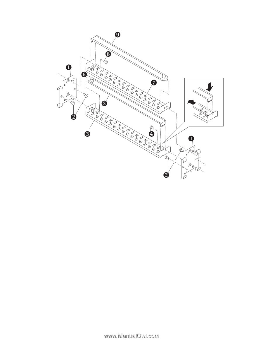
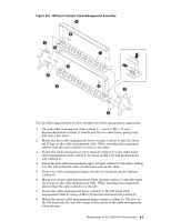
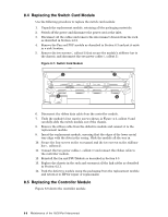
Figure 8-2: 16/32-port chassis Cable Management Assembly ` _ X ] ^ \ Y Z [ X Y Use the following procedure to first assemble the cable management components: 1. On each cable management slide (callout 1) , screw 2 M4 x 10 mm knurled-head bolts (callout 2) loosely into the two outer holes, giving each bolt only a few turns. 2. Mount the first cable management lower retainer (callout 3) onto the lower set of lugs on the cable management slide. When orienting this component, observe that the extra cutout is located on the right. 3. Secure the cable management lower retainer (callout 3) to the right hand cable management slide (callout 1) by using an M4 x 10 mm knurled-head bolt (callout 4) 4. Lower the first cable management upper retainer (callout 5) into place, sliding it to the left so that the tabs at both ends locate in the slots. 5. Secure the cable management upper retainer by using its captive fastener (callout 6). 6. Mount the second cable management lower retainer (callout 7) onto the upper set of lugs on the cable management slide. When orienting this component, observe that the extra cutout is on the left. 7. Secure the cable management lower retainer to the left hand cable management slide by using an M4 x 10 mm knurled-head bolt (callout 8). 8. Mount the second cable management upper retainer (callout 9). The slot on the left hand side fits over the tongue in the cutout of the cable management lower retainer. Maintenance of the 16/32-Port Interconnect 8-3
-
 1
1 -
2
-
3
-
4
-
5
-
6
-
7
-
8
-
9
-
10
-
11
-
12
-
13
-
14
-
15
-
16
-
17
-
18
-
19
-
20
-
21
-
22
-
23
-
24
-
25
-
26
-
27
-
28
-
29
-
30
-
31
-
32
-
33
-
34
-
35
-
36
-
37
-
38
-
39
-
40
-
41
-
42
-
43
-
44
-
45
-
46
-
47
-
48
-
49
-
50
-
51
-
52
-
53
-
54
-
55
-
56
-
57
-
58
-
59
-
60
-
61
-
62
-
63
-
 64
64 -
 65
65 -
 66
66 -
 67
67 -
 68
68 -
 69
69 -
 70
70 -
 71
71 -
 72
72 -
 73
73 -
 74
74 -
75
-
76
-
77
-
78
-
79
-
80
-
81
-
82
-
83
-
84
-
85
-
86
-
87
-
88
-
89
-
90
-
91
-
92
-
93
-
94
-
95
-
96
-
97
-
98
-
99
-
100
-
101
-
102
-
103
-
104
-
105
-
106
-
107
-
108
-
109
-
110
-
111
-
112
-
113
-
114
-
115
-
116
-
117
-
118
-
119
-
120
-
121
-
122
-
123
-
124
-
125
-
126
-
127
-
128
-
129
-
130
-
131
-
132
-
133
-
134
-
135
-
136
-
137
-
138
-
139
-
140
-
141
-
142
-
143
-
144
-
145
-
146
-
147
-
148
-
149
-
150
-
151
-
152
-
153
-
154
-
155
-
156
-
157
-
158
-
159
-
160
-
161
-
162
-
163
-
164
-
165
-
166
 |
 |