HP Cluster Platform Interconnects v2010 Quadrics QsNetII Interconnect - Page 28
Port and Slot Numbering, 2.3 Interconnect Enclosure Variations
 |
View all HP Cluster Platform Interconnects v2010 manuals
Add to My Manuals
Save this manual to your list of manuals |
Page 28 highlights
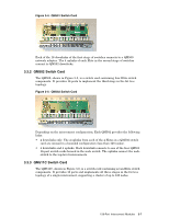
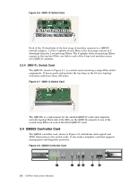
3.2.2 Port and Slot Numbering Figure 3-2 shows how the front slots are numbered in an enclosure. At the front of the switch, there are 5 vertical slots: 4 slots for the switch cards and one slot for the secondary QM503 controller card. These slots are numbered from right to left: 4 and 5, the secondary QM503 controller card, Ctrl B, and then 6 and 7. The 5 vertical slots at the rear of the switch can be populated with up to 4 switch cards. These rear slots are numbered 0 to 3 from left to right with the primary QM503 controller card, Ctrl A, in the middle. Ports are numbered from top to bottom, 0 to 15. Card 0 provides ports 0 to 15, card 1 provides ports 16 to 31, and so on. This numbering convention is used as part of a port numbering convention, creating a unique physical address (port ID) for every port in the interconnect. The port ID is used in the interconnect network cabling procedures, to create the network topology, Each cable has an identifying label that determines its port of origin and destination, as described in the cabling tables. 3.2.3 Interconnect Enclosure Variations The interconnect is modular and scalable. It is configured in three ways, as follows: • A standalone 16-port to 128-port, 3-stage interconnect, supporting configurations of up to 128 nodes, (see Section 3.2.3.1). • A node-level interconnect, forming three stages of a federated network, (see Section 3.2.3.2) • A top-level interconnect, forming stages four and five in a federated network of 256, 512, 1024 or a theoretical maximum of 4096 nodes. The Cabling Tables provide definitions of the interconnect configurations that are supported for HP Cluster Platform. 3.2.3.1 Interconnect Configuration for 16-128 Node Clusters For configurations of 16-128 nodes, QM511C and QM511L switch cards are installed. Each of the QM511C cards has 16 link ports. If less than 128 ports are required, QM511L cards are installed in the unused slots to complete the third stage of the network. The QM511L cards provide connectivity between the QM511C cards. In this configuration, interconnects provide a 3-stage fat tree topology, with all three stages implemented by the QM511C cards. External clock plugs must be fitted to the external clock inputs and the QM503 controller card must be configured to operate from the internal clock. Figure 3-2 and Figure 3-3 provide front and rear views of the interconnect in the full 128-port configuration, with all slots occupied. 3-4 128-Port Interconnect Modules
-
 1
1 -
2
-
3
-
4
-
5
-
6
-
7
-
8
-
9
-
10
-
11
-
12
-
13
-
14
-
15
-
16
-
17
-
18
-
19
-
20
-
21
-
22
-
 23
23 -
 24
24 -
 25
25 -
 26
26 -
 27
27 -
 28
28 -
 29
29 -
 30
30 -
 31
31 -
 32
32 -
 33
33 -
34
-
35
-
36
-
37
-
38
-
39
-
40
-
41
-
42
-
43
-
44
-
45
-
46
-
47
-
48
-
49
-
50
-
51
-
52
-
53
-
54
-
55
-
56
-
57
-
58
-
59
-
60
-
61
-
62
-
63
-
64
-
65
-
66
-
67
-
68
-
69
-
70
-
71
-
72
-
73
-
74
-
75
-
76
-
77
-
78
-
79
-
80
-
81
-
82
-
83
-
84
-
85
-
86
-
87
-
88
-
89
-
90
-
91
-
92
-
93
-
94
-
95
-
96
-
97
-
98
-
99
-
100
-
101
-
102
-
103
-
104
-
105
-
106
-
107
-
108
-
109
-
110
-
111
-
112
-
113
-
114
-
115
-
116
-
117
-
118
-
119
-
120
-
121
-
122
-
123
-
124
-
125
-
126
-
127
-
128
-
129
-
130
-
131
-
132
-
133
-
134
-
135
-
136
-
137
-
138
-
139
-
140
-
141
-
142
-
143
-
144
-
145
-
146
-
147
-
148
-
149
-
150
-
151
-
152
-
153
-
154
-
155
-
156
-
157
-
158
-
159
-
160
-
161
-
162
-
163
-
164
-
165
-
166
 |
 |
