HP Cluster Platform Interconnects v2010 Quadrics QsNetII Interconnect - Page 16
HP Cluster Platform.
 |
View all HP Cluster Platform Interconnects v2010 manuals
Add to My Manuals
Save this manual to your list of manuals |
Page 16 highlights
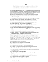
interconnects must be configured differently as node-level and top-level interconnects. The interconnects are linked into a hierarchy to create all levels of the fat tree network topology. Such clusters are described as federated. The type of cluster is determined by the customer's order, and is specified by the bill of materials (BOM) generated by that order. Important There are specific variations in cabling that are determined by the BOM for a modular cluster. Ensure that you use the correct cabling table variant according to the BOM. The generic procedure for cabling is as follows: 1. Prepare for the installation by reading the Cluster Platform Overview, which describes the naming conventions for cluster components, such as node types, building blocks, and connection topology. 2. Determine the model of servers used in the cluster and identify the cable management systems used for the server models and for the interconnect (Quadrics). The cable management installation guides are provided on the documentation CD-ROM. 3. Complete any rack assembly work and organize the racks as described in the Site Preparation Guide and the site plan. 4. Confirm that the rack's main breaker and breakers 1-4 on the main PDU are in the Off position (switched to the right). Do not apply power to the cluster until the cabling procedures are complete. 5. Determine which type cluster you are working on: • Bounded clusters of 16 to 128 nodes, reduced bandwidth. • Bounded clusters 16 to 64 nodes, full bandwidth. • Federated clusters of 129 to 1024 nodes, reduced bandwidth. • Federated clusters of 129 to 1024 nodes, full bandwidth. 6. Determine the configuration of the interconnect, according to the configuration rules described in the Cabling Tables for your model and configuration of HP Cluster Platform. 7. Determine the total interconnect components (parts) requirement as specified in Appendix A. 8. If not already configured (which is the usual delivery state), configure the interconnects using the rules that you determined in Step 3, and the interconnect component options described in Appendix B. 9. Read the port identification rules in the Cabling Tables for your interconnect type. 10. According to the cluster type that you determined in Step 2, consult the cabling tables for your model and configuration of HP Cluster Platform. Select the appropriate cabling chart depending on whether the server format is 1U, 2U, or 4U height. Important Ensure that you identify and follow any rules for alternate cabling, according to node and module specifications in the BOM. For example, the cluster configuration might require a link between the control node and the interconnect (an option). Other alternate 1-6 Overview of Quadrics-Based Clusters
-
 1
1 -
2
-
3
-
4
-
5
-
6
-
7
-
8
-
9
-
10
-
 11
11 -
 12
12 -
 13
13 -
 14
14 -
 15
15 -
 16
16 -
 17
17 -
 18
18 -
 19
19 -
 20
20 -
 21
21 -
22
-
23
-
24
-
25
-
26
-
27
-
28
-
29
-
30
-
31
-
32
-
33
-
34
-
35
-
36
-
37
-
38
-
39
-
40
-
41
-
42
-
43
-
44
-
45
-
46
-
47
-
48
-
49
-
50
-
51
-
52
-
53
-
54
-
55
-
56
-
57
-
58
-
59
-
60
-
61
-
62
-
63
-
64
-
65
-
66
-
67
-
68
-
69
-
70
-
71
-
72
-
73
-
74
-
75
-
76
-
77
-
78
-
79
-
80
-
81
-
82
-
83
-
84
-
85
-
86
-
87
-
88
-
89
-
90
-
91
-
92
-
93
-
94
-
95
-
96
-
97
-
98
-
99
-
100
-
101
-
102
-
103
-
104
-
105
-
106
-
107
-
108
-
109
-
110
-
111
-
112
-
113
-
114
-
115
-
116
-
117
-
118
-
119
-
120
-
121
-
122
-
123
-
124
-
125
-
126
-
127
-
128
-
129
-
130
-
131
-
132
-
133
-
134
-
135
-
136
-
137
-
138
-
139
-
140
-
141
-
142
-
143
-
144
-
145
-
146
-
147
-
148
-
149
-
150
-
151
-
152
-
153
-
154
-
155
-
156
-
157
-
158
-
159
-
160
-
161
-
162
-
163
-
164
-
165
-
166
 |
 |