HP Cluster Platform Interconnects v2010 Quadrics QsNetII Interconnect - Page 90
Event, Node LED Display QM500 array, Switch Card LED Display, Node-level Interconnect LEDs, Top-
 |
View all HP Cluster Platform Interconnects v2010 manuals
Add to My Manuals
Save this manual to your list of manuals |
Page 90 highlights
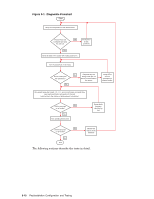
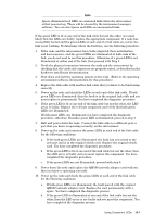
and the switch cards in the interconnect. A link can be node-to-interconnect, or interconnect-to-interconnect for federated configurations. The link LEDs are located on QM500 PCI cards in nodes, and on the switch cards in the interconnect. Each card has a group of three red, amber, and green LEDs. Each LED has the following meaning when illuminated: • Red - An error has been detected since the registers were last cleared. • Amber (flashing) - Data traffic flowing on the link. • Green - The link is connected. Where two functional components are powered on and connected by a functional link cable, the green LEDs are illuminated. An illuminated red LED indicates that a component or the link cable might be faulty. The fault might only be an installation problem, such as a card that is not correctly seated in the slot or a cable that is not securely seated in a port. During a normal (error free) initialization and run sequence you will see two different patterns of LED illumination as follows: • LED illumination during node boot is described in Section 10.2.1.1. • LED illumination during interconnect power up is described in Section 10.2.1.2. 10.2.1.1 Power on and Boot a Node The red, amber, and green LEDs on the link components provide the following diagnostic information as you power on and boot each node. Event Node LED Display (QM500 array) Node connected No LEDs illuminated Node on Green illuminated Node boot Green illuminated. Amber flashes briefly. Node at login Green illuminated System run Green illuminated. Amber illuminated intermittently or continuously (data traffic). Switch Card LED Display Red illuminated Green and red illuminated Green and red illuminated Green illuminated Green illuminated 10.2.1.2 Power on the Interconnects The red, amber, and green LED arrays on the interconnect port provide the following diagnostic information as you power on each interconnect: Event Node-level Interconnect LEDs NLI off, TLI off No LEDs illuminated NLI on, TLI off Red illuminated NLI on, TLI on Red illuminated Link to NLI only Red illuminated Link to TLI only Red illuminated Link from NLI Green illuminated to TLI System run Green illuminated. Amber illuminated intermittently or continuously (data traffic). Top-level Interconnect LEDs No LEDs illuminated No LEDs illuminated Red illuminated Red illuminated Red illuminated Green illuminated Green illuminated See Section 10.3 for information on using the LEDs to diagnose link problems. 10-4 Using Component LEDs
-
 1
1 -
2
-
3
-
4
-
5
-
6
-
7
-
8
-
9
-
10
-
11
-
12
-
13
-
14
-
15
-
16
-
17
-
18
-
19
-
20
-
21
-
22
-
23
-
24
-
25
-
26
-
27
-
28
-
29
-
30
-
31
-
32
-
33
-
34
-
35
-
36
-
37
-
38
-
39
-
40
-
41
-
42
-
43
-
44
-
45
-
46
-
47
-
48
-
49
-
50
-
51
-
52
-
53
-
54
-
55
-
56
-
57
-
58
-
59
-
60
-
61
-
62
-
63
-
64
-
65
-
66
-
67
-
68
-
69
-
70
-
71
-
72
-
73
-
74
-
75
-
76
-
77
-
78
-
79
-
80
-
81
-
82
-
83
-
84
-
 85
85 -
 86
86 -
 87
87 -
 88
88 -
 89
89 -
 90
90 -
 91
91 -
 92
92 -
 93
93 -
 94
94 -
 95
95 -
96
-
97
-
98
-
99
-
100
-
101
-
102
-
103
-
104
-
105
-
106
-
107
-
108
-
109
-
110
-
111
-
112
-
113
-
114
-
115
-
116
-
117
-
118
-
119
-
120
-
121
-
122
-
123
-
124
-
125
-
126
-
127
-
128
-
129
-
130
-
131
-
132
-
133
-
134
-
135
-
136
-
137
-
138
-
139
-
140
-
141
-
142
-
143
-
144
-
145
-
146
-
147
-
148
-
149
-
150
-
151
-
152
-
153
-
154
-
155
-
156
-
157
-
158
-
159
-
160
-
161
-
162
-
163
-
164
-
165
-
166
 |
 |
