HP Cluster Platform Interconnects v2010 Quadrics QsNetII Interconnect - Page 58
Caution, Inserting a Fan Tray
 |
View all HP Cluster Platform Interconnects v2010 manuals
Add to My Manuals
Save this manual to your list of manuals |
Page 58 highlights
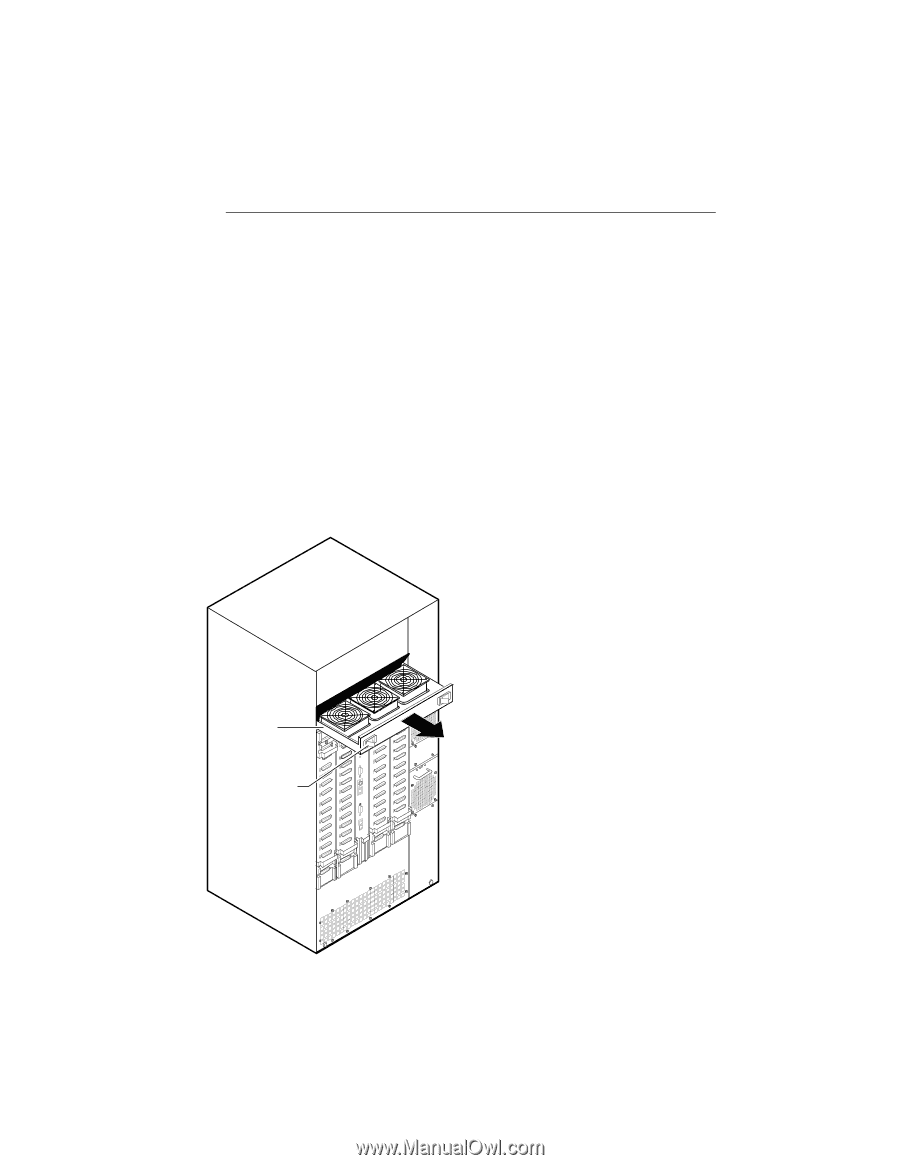
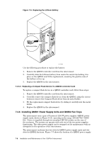
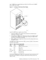
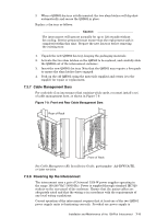
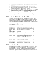
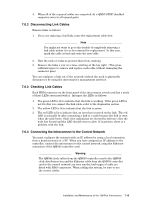
Use the following procedure to replace a power supply: Caution If you remove a QM561 while the interconnect is powered up, do not leave the system running unattended and do not insert anything other than a replacement QM561 in the vacant slot. 1. Unpack the new QM561 power supply unit, keeping the packaging materials. 2. Check the status of both the QM561 to be replaced and the QM561 that is to remain in the interconnect. Ensure that the QM561 that is to remain in the interconnect is operating correctly. 3. Activate the release latch on the QM561 to be replaced and carefully slide the module out of the interconnect. 4. Insert the replacement QM561 power supply unit and slide it into the slot until the connector is docked and the latching mechanism is activated. 5. Ensure that the replacement QM561 is operating correctly. 6. Pack up the old QM561 power supply unit using the materials supplied and return it to the supplier for repair or replacement. Figure 7-8 shows the location of a fan tray. Figure 7-8: Inserting a Fan Tray QUaDrics QsNet" PSU A Fan Tray PSU B Slam Latches HPTC-0031 Install the fan trays as follows: 1. Unpack the QM562 fan trays, shown in Figure 6.12. 2. If you are fitting only one QM562 fan tray, insert it into slot Fan A and fit slot Fan B with a QM563 fan tray blank. If you are fitting two QM562 fan trays, insert them in slots Fan A and Fan B. 7-10 Installation and Maintenance of the 128-Port Interconnect
-
 1
1 -
2
-
3
-
4
-
5
-
6
-
7
-
8
-
9
-
10
-
11
-
12
-
13
-
14
-
15
-
16
-
17
-
18
-
19
-
20
-
21
-
22
-
23
-
24
-
25
-
26
-
27
-
28
-
29
-
30
-
31
-
32
-
33
-
34
-
35
-
36
-
37
-
38
-
39
-
40
-
41
-
42
-
43
-
44
-
45
-
46
-
47
-
48
-
49
-
50
-
51
-
52
-
 53
53 -
 54
54 -
 55
55 -
 56
56 -
 57
57 -
 58
58 -
 59
59 -
 60
60 -
 61
61 -
 62
62 -
 63
63 -
64
-
65
-
66
-
67
-
68
-
69
-
70
-
71
-
72
-
73
-
74
-
75
-
76
-
77
-
78
-
79
-
80
-
81
-
82
-
83
-
84
-
85
-
86
-
87
-
88
-
89
-
90
-
91
-
92
-
93
-
94
-
95
-
96
-
97
-
98
-
99
-
100
-
101
-
102
-
103
-
104
-
105
-
106
-
107
-
108
-
109
-
110
-
111
-
112
-
113
-
114
-
115
-
116
-
117
-
118
-
119
-
120
-
121
-
122
-
123
-
124
-
125
-
126
-
127
-
128
-
129
-
130
-
131
-
132
-
133
-
134
-
135
-
136
-
137
-
138
-
139
-
140
-
141
-
142
-
143
-
144
-
145
-
146
-
147
-
148
-
149
-
150
-
151
-
152
-
153
-
154
-
155
-
156
-
157
-
158
-
159
-
160
-
161
-
162
-
163
-
164
-
165
-
166
 |
 |