HP Cluster Platform Interconnects v2010 Quadrics QsNetII Interconnect - Page 55
Replacing a QM503 controller Card, 3.5.2, Replacing a Lithium Battery in a QM503 Controller
 |
View all HP Cluster Platform Interconnects v2010 manuals
Add to My Manuals
Save this manual to your list of manuals |
Page 55 highlights
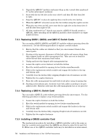
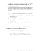
depending on whether redundant operation is required for the end user installation. Note that if only one QM503 is fitted (no redundancy), use slot Ctrl A only. 7.3.5.1 Replacing a QM503 controller Card You can replace QM503 controller cards without powering down the interconnect provided that two modules are fitted to provide redundancy. The procedure to replace a QM503 controller card is as follows. If only one QM503 controller card is fitted then turn off the power to both QM561 power supply units and proceed from step 4: 1. Identify the QM503 to be replaced. 2. Press the Shutdown button using a pen tip (or similar) so that the module to be replaced is disabled gracefully. Failure to do this can cause undefined system errors. 3. Wait until the green LED labelled Ctrl Run is extinguished and the red LED labeled Ctrl Error is lit. 4. Disconnect all cables. 5. Loosen the captive fastener on each of the latches. 6. Eject the QM503 by opening its two latches simultaneously. 7. Slide in the replacement QM503 controller card and engage the latches in the top and bottom rails. 8. Carefully close the latches fully, stopping if high levels of resistance are felt. 9. Tighten the two captive fasteners. 10. Reconnect the cables. 11. Turn the power back on, if you powered down the interconnect at the start of the procedure. 7.3.5.2 Replacing a Lithium Battery in a QM503 Controller Card Figure 7-6 shows the location of the lithium battery. Caution There is a danger of explosion if the Lithium battery is incorrectly replaced. Replace only with a type CR2032 battery or equivalent. Dispose of used batteries according to the manufacturer's instructions. Installation and Maintenance of the 128-Port Interconnect 7-7
-
 1
1 -
2
-
3
-
4
-
5
-
6
-
7
-
8
-
9
-
10
-
11
-
12
-
13
-
14
-
15
-
16
-
17
-
18
-
19
-
20
-
21
-
22
-
23
-
24
-
25
-
26
-
27
-
28
-
29
-
30
-
31
-
32
-
33
-
34
-
35
-
36
-
37
-
38
-
39
-
40
-
41
-
42
-
43
-
44
-
45
-
46
-
47
-
48
-
49
-
 50
50 -
 51
51 -
 52
52 -
 53
53 -
 54
54 -
 55
55 -
 56
56 -
 57
57 -
 58
58 -
 59
59 -
 60
60 -
61
-
62
-
63
-
64
-
65
-
66
-
67
-
68
-
69
-
70
-
71
-
72
-
73
-
74
-
75
-
76
-
77
-
78
-
79
-
80
-
81
-
82
-
83
-
84
-
85
-
86
-
87
-
88
-
89
-
90
-
91
-
92
-
93
-
94
-
95
-
96
-
97
-
98
-
99
-
100
-
101
-
102
-
103
-
104
-
105
-
106
-
107
-
108
-
109
-
110
-
111
-
112
-
113
-
114
-
115
-
116
-
117
-
118
-
119
-
120
-
121
-
122
-
123
-
124
-
125
-
126
-
127
-
128
-
129
-
130
-
131
-
132
-
133
-
134
-
135
-
136
-
137
-
138
-
139
-
140
-
141
-
142
-
143
-
144
-
145
-
146
-
147
-
148
-
149
-
150
-
151
-
152
-
153
-
154
-
155
-
156
-
157
-
158
-
159
-
160
-
161
-
162
-
163
-
164
-
165
-
166
 |
 |