HP Cluster Platform Interconnects v2010 Quadrics QsNetII Interconnect - Page 20
Interconnect Network Topology
 |
View all HP Cluster Platform Interconnects v2010 manuals
Add to My Manuals
Save this manual to your list of manuals |
Page 20 highlights
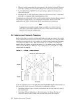
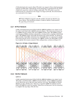
• Ethernet cables connecting the interconnect to the cluster's internal Ethernet networks, enabling access to built-in diagnostics and management programs. • A clock distribution (QM580) box for generating a global clock source in a federated network. • Shielded CAT-V clock distribution cables join all interconnects in a federated network to a common clock synchronization source. Components are referenced by the vendor's model numbers because these numbers are printed on parts labels or on component bezel labels. Refer to the field replaceable unit (FRU) table to find the HP equivalent part numbering. Note Component part numbers might change as models are revised. Always verify that a part and its firmware (if any) is of the correct revision and supports your current configuration. 2.2 Interconnect Network Topology Each switch chip in a switch card has eight link ports and can connect up to eight nodes. Clusters built around interconnects are constructed by connecting the Elite switches in a quaternary fat tree topology in which 4 links function as downlinks connecting to 4 cluster nodes. The other 4 links act as uplinks connecting to a higher stage of switches, as shown in Figure 2-1. The higher stage of switches interconnects all 16 nodes. This two stage configuration is packaged on a single switch card, the QM501. Figure 2-1: 16 Node, 2 Stage Network Uplinks to High-Level Cards 7 6 5 4 Stage 2 7 65 4 16-Port Switch Card 0 1 2 3 Stage 1 0123 16 Nodes A fat tree topology gives a very high bisectional bandwidth which scales linearly as the size of the cluster increases. Scaling is accomplished as follows: • Installing different types of switch card modules in the front and rear slots of the interconnect. • Installing different midplanes in the interconnect to change the type of connection between the switch cards on both sides of the interconnect. 2-2 Quadrics Interconnect Overview
-
 1
1 -
2
-
3
-
4
-
5
-
6
-
7
-
8
-
9
-
10
-
11
-
12
-
13
-
14
-
 15
15 -
 16
16 -
 17
17 -
 18
18 -
 19
19 -
 20
20 -
 21
21 -
 22
22 -
 23
23 -
 24
24 -
 25
25 -
26
-
27
-
28
-
29
-
30
-
31
-
32
-
33
-
34
-
35
-
36
-
37
-
38
-
39
-
40
-
41
-
42
-
43
-
44
-
45
-
46
-
47
-
48
-
49
-
50
-
51
-
52
-
53
-
54
-
55
-
56
-
57
-
58
-
59
-
60
-
61
-
62
-
63
-
64
-
65
-
66
-
67
-
68
-
69
-
70
-
71
-
72
-
73
-
74
-
75
-
76
-
77
-
78
-
79
-
80
-
81
-
82
-
83
-
84
-
85
-
86
-
87
-
88
-
89
-
90
-
91
-
92
-
93
-
94
-
95
-
96
-
97
-
98
-
99
-
100
-
101
-
102
-
103
-
104
-
105
-
106
-
107
-
108
-
109
-
110
-
111
-
112
-
113
-
114
-
115
-
116
-
117
-
118
-
119
-
120
-
121
-
122
-
123
-
124
-
125
-
126
-
127
-
128
-
129
-
130
-
131
-
132
-
133
-
134
-
135
-
136
-
137
-
138
-
139
-
140
-
141
-
142
-
143
-
144
-
145
-
146
-
147
-
148
-
149
-
150
-
151
-
152
-
153
-
154
-
155
-
156
-
157
-
158
-
159
-
160
-
161
-
162
-
163
-
164
-
165
-
166
 |
 |
