HP Cluster Platform Interconnects v2010 Quadrics QsNetII Interconnect - Page 66
refit the wiring harnesses.
 |
View all HP Cluster Platform Interconnects v2010 manuals
Add to My Manuals
Save this manual to your list of manuals |
Page 66 highlights
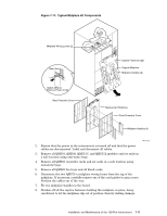
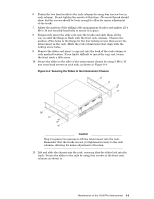
9. Tilt the bottom of the midplane towards you until it will clear the top of the module cage then, keeping it at this angle, slowly and carefully remove the midplane from the interconnect. 10. Take off the midplane handles and fit Midplane protective covers (if supplied with the replacement midplane). 11. Fitting a replacement QM540 or QM542 midplane is the reverse of removal, except that the front cover should be left in place until the midplane is installed in the interconnect. This provides protection for the midplane when securing it to the interconnect. 12. Ensure that all captive fasteners are tightened fully. Note that the midplane cover will have to be removed to gain access to some of the fasteners. 13. When the replacement midplane is secure, remove the midplane handles and refit the wiring harnesses. 14. Refit the modules removed, ensuring that all slots are filled to ensure full functionality and EMC compliance. 15. Reconnect the mains supply, power up the interconnect, and run the verification tests specified in the diagnostics information. 7-18 Installation and Maintenance of the 128-Port Interconnect
-
 1
1 -
2
-
3
-
4
-
5
-
6
-
7
-
8
-
9
-
10
-
11
-
12
-
13
-
14
-
15
-
16
-
17
-
18
-
19
-
20
-
21
-
22
-
23
-
24
-
25
-
26
-
27
-
28
-
29
-
30
-
31
-
32
-
33
-
34
-
35
-
36
-
37
-
38
-
39
-
40
-
41
-
42
-
43
-
44
-
45
-
46
-
47
-
48
-
49
-
50
-
51
-
52
-
53
-
54
-
55
-
56
-
57
-
58
-
59
-
60
-
 61
61 -
 62
62 -
 63
63 -
 64
64 -
 65
65 -
 66
66 -
 67
67 -
 68
68 -
 69
69 -
 70
70 -
 71
71 -
72
-
73
-
74
-
75
-
76
-
77
-
78
-
79
-
80
-
81
-
82
-
83
-
84
-
85
-
86
-
87
-
88
-
89
-
90
-
91
-
92
-
93
-
94
-
95
-
96
-
97
-
98
-
99
-
100
-
101
-
102
-
103
-
104
-
105
-
106
-
107
-
108
-
109
-
110
-
111
-
112
-
113
-
114
-
115
-
116
-
117
-
118
-
119
-
120
-
121
-
122
-
123
-
124
-
125
-
126
-
127
-
128
-
129
-
130
-
131
-
132
-
133
-
134
-
135
-
136
-
137
-
138
-
139
-
140
-
141
-
142
-
143
-
144
-
145
-
146
-
147
-
148
-
149
-
150
-
151
-
152
-
153
-
154
-
155
-
156
-
157
-
158
-
159
-
160
-
161
-
162
-
163
-
164
-
165
-
166
 |
 |