HP Cluster Platform Interconnects v2010 Quadrics QsNetII Interconnect - Page 50
Front
 |
View all HP Cluster Platform Interconnects v2010 manuals
Add to My Manuals
Save this manual to your list of manuals |
Page 50 highlights
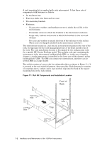
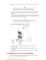
A rack mounting kit is supplied with each interconnect. It has three sets of components with fasteners as follows: • An enclosure tray • Four tray slides (two front and two rear) • Two mounting brackets • Fasteners: - 12 cage nuts, washers, and machine screws to attach the rail kit to the rack columns. - 16 machine screws to attach the brackets to the interconnect enclosure. - 6 cage nuts, washers and screws to attach the brackets to the rear rack columns. - Two nuts and washers to attach the front of the enclosure to the rail kit. (These nuts are shipped installed on the interconnect enclosure). The interconnect mounts on a rail kit and is secured by brackets to the rear of the rack, leaving space for the cable management bars at the front and the rear of the rack. The rack installation location is determined by the configuration rules for a specific HP Cluster Platform model. The modular rack unit containing the interconnect is the interconnect building block (IBB), or, in the case of smaller clusters, a single interconnect is installed in the lower part of the cluster's utility building block (UBB). The IBB can contain two interconnect, and there can be several IBBs in a large cluster. The rail kit consists of a tray with four adjustable slides as shown in Figure 7-1. It is secured to the rack with 12 fasteners, three per slide. Each fastener set consists of a machine screw, washer, and a cage nut that clips into the back of the square mounting hole in the rack column. Figure 7-1: Rail Kit Components and Installation Location Front of Rack Right Rear Slide Left Rear Slide Tray Right Front Slide Left Front Slide 7-2 Installation and Maintenance of the 128-Port Interconnect
-
 1
1 -
2
-
3
-
4
-
5
-
6
-
7
-
8
-
9
-
10
-
11
-
12
-
13
-
14
-
15
-
16
-
17
-
18
-
19
-
20
-
21
-
22
-
23
-
24
-
25
-
26
-
27
-
28
-
29
-
30
-
31
-
32
-
33
-
34
-
35
-
36
-
37
-
38
-
39
-
40
-
41
-
42
-
43
-
44
-
 45
45 -
 46
46 -
 47
47 -
 48
48 -
 49
49 -
 50
50 -
 51
51 -
 52
52 -
 53
53 -
 54
54 -
 55
55 -
56
-
57
-
58
-
59
-
60
-
61
-
62
-
63
-
64
-
65
-
66
-
67
-
68
-
69
-
70
-
71
-
72
-
73
-
74
-
75
-
76
-
77
-
78
-
79
-
80
-
81
-
82
-
83
-
84
-
85
-
86
-
87
-
88
-
89
-
90
-
91
-
92
-
93
-
94
-
95
-
96
-
97
-
98
-
99
-
100
-
101
-
102
-
103
-
104
-
105
-
106
-
107
-
108
-
109
-
110
-
111
-
112
-
113
-
114
-
115
-
116
-
117
-
118
-
119
-
120
-
121
-
122
-
123
-
124
-
125
-
126
-
127
-
128
-
129
-
130
-
131
-
132
-
133
-
134
-
135
-
136
-
137
-
138
-
139
-
140
-
141
-
142
-
143
-
144
-
145
-
146
-
147
-
148
-
149
-
150
-
151
-
152
-
153
-
154
-
155
-
156
-
157
-
158
-
159
-
160
-
161
-
162
-
163
-
164
-
165
-
166
 |
 |
