HP Cluster Platform Interconnects v2010 Quadrics QsNetII Interconnect - Page 99
Warning
 |
View all HP Cluster Platform Interconnects v2010 manuals
Add to My Manuals
Save this manual to your list of manuals |
Page 99 highlights
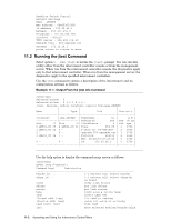
modules id . quit exit reset roms addr_start [addr_end] elitereadrom addr data [mask] elitewriterom addr data [mask] toggle_fed vpd scan state environment verbose write instr data [mask] (-1 selects all) select modules quit jtest quit jtest reset jtag read board level EEPROM 50X read elite EEPROM write elite EEPROM module config - toggle federated read vital product data boundary scan get link state get temperature/fan/psu info toggle verbose mode jtag write Warning Use only the command options listed below, and ensure that you run commands at appropriate times. Options other than those listed below can cause jobs to crash, and might also cause damage to cluster components. The command options supported for HP Cluster Platform are as follows: • Operations are applied to selected chips on the selected boards as follows: boards id ... chips id ... (-1 selects all) select boards (-1 selects all) select chips(s) on board Boards and chips are selected by ID using these options. An ID of -1 selects all boards or chips. • clear - Clears network errors on the selected chips. • delays - Interconnect links tune themselves to the electrical characteristics of the link/cable. The delays option prints this tuning information for each signal wire. As shown in the following example: Board 0 Elite 0 link delays D0 D1 D2 D3 D4 D5 D6 D7 D8 PLL Clock LIn L0: 041 039 028 031 037 034 029 033 040 032 204 222 L1: 096 112 090 091 071 093 076 077 071 031 000 3dd L2: 031 037 041 040 031 053 047 053 045 015 005 3ff L3: 059 038 039 036 044 028 030 022 033 031 206 1dd L4: 081 084 085 084 088 093 092 093 096 031 000 062 L5: 037 032 039 032 039 033 035 030 032 031 004 3dd L6: 070 070 077 077 079 085 085 088 090 016 200 1dd L7: 041 034 038 033 039 036 034 031 031 031 004 222 The values printed depend on the relative lengths of the individual wires in the cable. Internal links on a switch card should show smaller differences than the values for link cables. • errors - Prints a report of errors on the selected chips. With the verbose option, all links are shown. Without it, only connected links are shown. The following example shows a single line of error output: B:C:L E RtCRC TrCRC RcvLk Dskew Phase Fifo0 Fifo1 OpenT PktRT ChM45 DataE Value 0:0:0 1 0 0 10 0 1 1 1 0 0 0 0 This output is defined in Section 12.8. • info - Prints information on the network, selected boards and selected chip Accessing and Using the Interconnect Control Menu 11-3
-
 1
1 -
2
-
3
-
4
-
5
-
6
-
7
-
8
-
9
-
10
-
11
-
12
-
13
-
14
-
15
-
16
-
17
-
18
-
19
-
20
-
21
-
22
-
23
-
24
-
25
-
26
-
27
-
28
-
29
-
30
-
31
-
32
-
33
-
34
-
35
-
36
-
37
-
38
-
39
-
40
-
41
-
42
-
43
-
44
-
45
-
46
-
47
-
48
-
49
-
50
-
51
-
52
-
53
-
54
-
55
-
56
-
57
-
58
-
59
-
60
-
61
-
62
-
63
-
64
-
65
-
66
-
67
-
68
-
69
-
70
-
71
-
72
-
73
-
74
-
75
-
76
-
77
-
78
-
79
-
80
-
81
-
82
-
83
-
84
-
85
-
86
-
87
-
88
-
89
-
90
-
91
-
92
-
93
-
 94
94 -
 95
95 -
 96
96 -
 97
97 -
 98
98 -
 99
99 -
 100
100 -
 101
101 -
 102
102 -
 103
103 -
 104
104 -
105
-
106
-
107
-
108
-
109
-
110
-
111
-
112
-
113
-
114
-
115
-
116
-
117
-
118
-
119
-
120
-
121
-
122
-
123
-
124
-
125
-
126
-
127
-
128
-
129
-
130
-
131
-
132
-
133
-
134
-
135
-
136
-
137
-
138
-
139
-
140
-
141
-
142
-
143
-
144
-
145
-
146
-
147
-
148
-
149
-
150
-
151
-
152
-
153
-
154
-
155
-
156
-
157
-
158
-
159
-
160
-
161
-
162
-
163
-
164
-
165
-
166
 |
 |