HP Cluster Platform Interconnects v2010 Quadrics QsNetII Interconnect - Page 38
Cabling the 16/32-Port Interconnect
 |
View all HP Cluster Platform Interconnects v2010 manuals
Add to My Manuals
Save this manual to your list of manuals |
Page 38 highlights
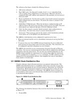
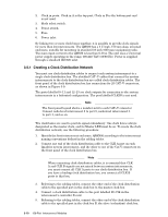
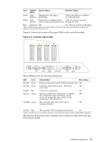
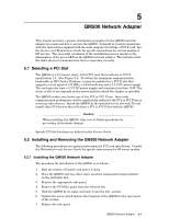
3. A single Infiniband port of the 16 ports or 32 ports in the switch card module, with its integrated EMI shielding. 4. Port status 3-LED array (green, amber, and red). 5. Controller card status array (green, green, and red). 6. Reset button (recessed to prevent accidental operation). 7. The connection ports for the controller card. These ports are defined in a later section. 8. Captive screws that secure the switch card module in the interconnect chassis (2 of 4 screws indicated). A further two screws secure the module inside the chassis. The opposite side of the unit contains a fan module with three cooling fans for front-to-rear cooling, as shown in . The fan module is secured in the interconnect chassis by the four captive screws shown at each corner of the module. Figure 4-2: 16/32-Port Interconnect, Rear View QsNetII Table 4-1 shows the characteristics of both models. Table 4-1: 16/32-Port Interconnect Models and Characteristics Model Link Speed Bandwidth Architecture 3X-CS32A-CA (16-port) 3X-CS32A-AA (32-port) Full duplex 10 bit, 1.3 G/baud Quadrics QsNetII link 14.4 Gb/s bisectional bandwidth 28.2 Gb/s bisectional bandwidth 2-stage fat tree architecture 4.2 Cabling the 16/32-Port Interconnect To ensure that the operation of the interconnect meets its performance criteria, adhere to the following cabling prerequisites: • All data I/O connections must be made using cable assemblies supplied by HP these cables assembles comply with the specifications for Quadrics links. • Ensure that the cables are fully inserted, locked in position and have the required support to ensure connector mating angles are within the acceptable 10 degree limit. • Replace cables if they show any signs of damage. • Cover all unused connector ports with shielded covers installed. 4-2 16/32-Port Interconnect
-
 1
1 -
2
-
3
-
4
-
5
-
6
-
7
-
8
-
9
-
10
-
11
-
12
-
13
-
14
-
15
-
16
-
17
-
18
-
19
-
20
-
21
-
22
-
23
-
24
-
25
-
26
-
27
-
28
-
29
-
30
-
31
-
32
-
 33
33 -
 34
34 -
 35
35 -
 36
36 -
 37
37 -
 38
38 -
 39
39 -
 40
40 -
 41
41 -
 42
42 -
 43
43 -
44
-
45
-
46
-
47
-
48
-
49
-
50
-
51
-
52
-
53
-
54
-
55
-
56
-
57
-
58
-
59
-
60
-
61
-
62
-
63
-
64
-
65
-
66
-
67
-
68
-
69
-
70
-
71
-
72
-
73
-
74
-
75
-
76
-
77
-
78
-
79
-
80
-
81
-
82
-
83
-
84
-
85
-
86
-
87
-
88
-
89
-
90
-
91
-
92
-
93
-
94
-
95
-
96
-
97
-
98
-
99
-
100
-
101
-
102
-
103
-
104
-
105
-
106
-
107
-
108
-
109
-
110
-
111
-
112
-
113
-
114
-
115
-
116
-
117
-
118
-
119
-
120
-
121
-
122
-
123
-
124
-
125
-
126
-
127
-
128
-
129
-
130
-
131
-
132
-
133
-
134
-
135
-
136
-
137
-
138
-
139
-
140
-
141
-
142
-
143
-
144
-
145
-
146
-
147
-
148
-
149
-
150
-
151
-
152
-
153
-
154
-
155
-
156
-
157
-
158
-
159
-
160
-
161
-
162
-
163
-
164
-
165
-
166
 |
 |
