HP Cluster Platform Interconnects v2010 Quadrics QsNetII Interconnect - Page 60
Configuring the QM503 controller Card
 |
View all HP Cluster Platform Interconnects v2010 manuals
Add to My Manuals
Save this manual to your list of manuals |
Page 60 highlights
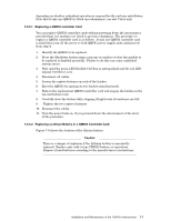
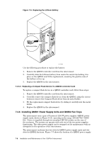
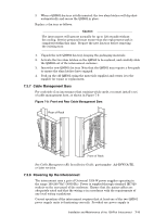
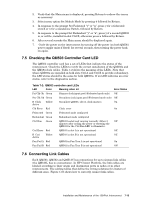
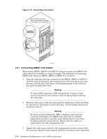
functioning, you can swap the other out for maintenance with no disruption to the operation of the interconnect. When powered up, normal operation of each QM561 power supply unit is indicated by the illumination of the following LEDs: Label AC OK DC OK Fault Over Temp Color Green Green Red Red Status On On Off Off 7.3.9 Connecting Federated Interconnects to an External Clock Source The connection to the clock box depends on whether the interconnect has a single controller card or dual controller cards. Note All clock I/O connections must be made using QM584 CAT-VE double-screened (foil and braid) cables approved by Quadrics. 7.3.9.1 Connecting a Single QM503 controller Card If the interconnect is part of a federated switch, connect QM584 clock cables to the QM503, installed in slot Ctrl A, as follows: 1. Connect the Pri Clk input on the QM503 to a clock output from a QM580 clock distribution box that is configured as a Master. 2. If the federated switch has more than one QM580 clock distribution box, connect the Sec Clk input on the QM503 to a clock output from a QM580 that is configured as a Slave. 7.3.9.2 Connecting Dual QM503 controller Cards If the interconnect is part of a federated switch, connect QM584 clock cables to the dual QM503 controller cards as follows: 1. Connect the Pri Clk input on the QM503 in slot Ctrl A to a clock output from a QM580 clock distribution box that is configured as a Master. 2. Connect the Pri Clk input on the QM503 in slot Ctrl B to a clock output from a QM580 clock distribution box that is configured as a Slave. 3. Do not connect the Sec Clk inputs on either of the QM503 modules. See Chapter 6. 7.4 Configuring the QM503 controller Card To verify that the interconnect is cabled to each QM580 clock distribution box correctly and that it is operating correctly, the operating mode of the QM503 controller card in slot Ctrl A must be configured. Note that the QM503 in slot Ctrl B (if fitted) is configured automatically to match. To configure the operating mode of the QM503, follow these steps: 1. Connect a VGA monitor and keyboard to the QM503 using the connectors labeled VGA and Kybd respectively. Alternatively, use a Null modem cable to connect the COM port of a PC to the serial port connector labelled COM 1. Configure the comport for 9600 Baud, no parity, 8 bits and 1 stop bit. Use a terminal emulator program to open a connection. 7-12 Installation and Maintenance of the 128-Port Interconnect
-
 1
1 -
2
-
3
-
4
-
5
-
6
-
7
-
8
-
9
-
10
-
11
-
12
-
13
-
14
-
15
-
16
-
17
-
18
-
19
-
20
-
21
-
22
-
23
-
24
-
25
-
26
-
27
-
28
-
29
-
30
-
31
-
32
-
33
-
34
-
35
-
36
-
37
-
38
-
39
-
40
-
41
-
42
-
43
-
44
-
45
-
46
-
47
-
48
-
49
-
50
-
51
-
52
-
53
-
54
-
 55
55 -
 56
56 -
 57
57 -
 58
58 -
 59
59 -
 60
60 -
 61
61 -
 62
62 -
 63
63 -
 64
64 -
 65
65 -
66
-
67
-
68
-
69
-
70
-
71
-
72
-
73
-
74
-
75
-
76
-
77
-
78
-
79
-
80
-
81
-
82
-
83
-
84
-
85
-
86
-
87
-
88
-
89
-
90
-
91
-
92
-
93
-
94
-
95
-
96
-
97
-
98
-
99
-
100
-
101
-
102
-
103
-
104
-
105
-
106
-
107
-
108
-
109
-
110
-
111
-
112
-
113
-
114
-
115
-
116
-
117
-
118
-
119
-
120
-
121
-
122
-
123
-
124
-
125
-
126
-
127
-
128
-
129
-
130
-
131
-
132
-
133
-
134
-
135
-
136
-
137
-
138
-
139
-
140
-
141
-
142
-
143
-
144
-
145
-
146
-
147
-
148
-
149
-
150
-
151
-
152
-
153
-
154
-
155
-
156
-
157
-
158
-
159
-
160
-
161
-
162
-
163
-
164
-
165
-
166
 |
 |