HP Cluster Platform Interconnects v2010 Quadrics QsNetII Interconnect - Page 37
Overview of the 16/32-Port Interconnect
 |
View all HP Cluster Platform Interconnects v2010 manuals
Add to My Manuals
Save this manual to your list of manuals |
Page 37 highlights
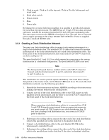
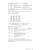
4 16/32-Port Interconnect Smaller clusters are optionally built using the Quadrics model QS32A 16/32-port interconnect. The following information is provided for this component: • An overview of the interconnect is provided in Section 4.1 • Instructions for cabling the 16/32-port interconnect are provided in Section 4.2 • An explanation of the 16/32-port interconnect signal LEDs is provided in Section 4.3 4.1 Overview of the 16/32-Port Interconnect The Quadrics® QsNetII™ model QS32A 16-port or 32-port interconnect is an option for smaller clusters of 8 to 32 nodes. The QS32A, shown in Figure 4-1, is a rack-mountable, high-speed switch unit with integrated power supply and controller. It provides 16 or 32 link ports for connecting up to 32 separate cluster nodes, each fitted with a QM500 host bus adapter (HBA). Figure 4-1: 16/32-Port Interconnect, Port View _ ^ ] \ [Z YX The information in this section refers to the 32-port model and describes any features or procedures that differ for the 16-port model.Figure 4-1 shows the port switch module, containing 32 high-speed link ports, each with three status LEDs. The top row of ports from left to right are labeled 0 through 15. The bottom row of ports from right to left are labeled 16 to 31. The orientation of the lower row of link ports is a mirror image the upper row. On the 32-port model, you must rotate the link cable connectors when you connect them to the lower ports. The following list of physical features are identified by the callouts in Figure 4-1: 1. The fuse-protected AC power inlet. 2. Power breaker switch. 16/32-Port Interconnect 4-1
-
 1
1 -
2
-
3
-
4
-
5
-
6
-
7
-
8
-
9
-
10
-
11
-
12
-
13
-
14
-
15
-
16
-
17
-
18
-
19
-
20
-
21
-
22
-
23
-
24
-
25
-
26
-
27
-
28
-
29
-
30
-
31
-
 32
32 -
 33
33 -
 34
34 -
 35
35 -
 36
36 -
 37
37 -
 38
38 -
 39
39 -
 40
40 -
 41
41 -
 42
42 -
43
-
44
-
45
-
46
-
47
-
48
-
49
-
50
-
51
-
52
-
53
-
54
-
55
-
56
-
57
-
58
-
59
-
60
-
61
-
62
-
63
-
64
-
65
-
66
-
67
-
68
-
69
-
70
-
71
-
72
-
73
-
74
-
75
-
76
-
77
-
78
-
79
-
80
-
81
-
82
-
83
-
84
-
85
-
86
-
87
-
88
-
89
-
90
-
91
-
92
-
93
-
94
-
95
-
96
-
97
-
98
-
99
-
100
-
101
-
102
-
103
-
104
-
105
-
106
-
107
-
108
-
109
-
110
-
111
-
112
-
113
-
114
-
115
-
116
-
117
-
118
-
119
-
120
-
121
-
122
-
123
-
124
-
125
-
126
-
127
-
128
-
129
-
130
-
131
-
132
-
133
-
134
-
135
-
136
-
137
-
138
-
139
-
140
-
141
-
142
-
143
-
144
-
145
-
146
-
147
-
148
-
149
-
150
-
151
-
152
-
153
-
154
-
155
-
156
-
157
-
158
-
159
-
160
-
161
-
162
-
163
-
164
-
165
-
166
 |
 |