HP Cluster Platform Interconnects v2010 Quadrics QsNetII Interconnect - Page 30
Switch Cards
 |
View all HP Cluster Platform Interconnects v2010 manuals
Add to My Manuals
Save this manual to your list of manuals |
Page 30 highlights
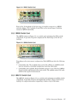
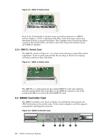
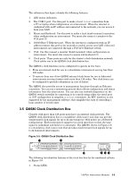
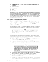
3.2.3.2.1 Node-Level Interconnect (NLI) Node level interconnects use the 3X-CS5A0-AF midplane. 4 QM502 switch cards are inserted in slots 0 through 3 in the rear of the enclosure. 4 QM501 switch cards are inserted in slots 4 through 7 in the front of the enclosure. Each of the QM501 cards has 16 link ports, making 64 ports in a fully populated enclosure. The port numbers on the QM501 and QM502 cards start at the top and are numbered 0-15. Node level interconnects use the 3X-CS5A0-AF midplane. 4 QM502 switch cards are inserted in slots 0 through 3 in the rear of the enclosure. 4 QM501 switch cards are inserted in slots 4 through 7 in the front of the enclosure. Each of the QM501 cards has 16 link ports, making 64 ports in a fully populated enclosure. The port numbers on the QM501 and QM502 cards start at the top and are numbered 0-15. You must connect a shielded CAT-V clock distribution cable must be connected between both Ctrl A and Ctrl B primary inputs to the appropriate the QM580 clock distribution box to ensure that the federated interconnects operate at a common frequency. The Ctrl A and Ctrl B secondary inputs can be attached to a second QM580 to provide backup in case of failure. The cabling tables describe the clock distribution network. 3.2.3.2.2 Reduced Bandwidth Federated Configurations HP Cluster Platforms can be configured to provide a lower bandwidth interconnect network at lower cost to the customer. In such configurations, fewer QM502 cards are installed in the front slots of the node-level interconnect. 3.2.3.2.3 Top-Level Interconnect (TLI) Table 3-2 shows the configuration rules for top-level interconnects. Table 3-2: TLI Configuration Rules Nodes Card Type 129-256 QM502 257-1024 QM501 Midplane 3X-CM5A0-AN 3X-CM5A0-AN All slots (front and rear) are populated with the specified card type, depending on the number of nodes in the cluster. Link cables connect the switch cards in the top-level interconnects to the QM502 cards in the front slots of the node-level interconnects. 3.3 Switch Cards The following sections describe the three switch card options, depending on the interconnect configuration. Cards are keyed to prevent incorrect insertion into midplanes that are not designed to receive the card. 3.3.1 QM501 Switch Card The QM501, shown in Figure 3-4, is a network switch card built from eight Elite switch components. These eight switches are arranged in a 2-stage, fat tree topology to produce a 16-way switch. 3-6 128-Port Interconnect Modules
-
 1
1 -
2
-
3
-
4
-
5
-
6
-
7
-
8
-
9
-
10
-
11
-
12
-
13
-
14
-
15
-
16
-
17
-
18
-
19
-
20
-
21
-
22
-
23
-
24
-
 25
25 -
 26
26 -
 27
27 -
 28
28 -
 29
29 -
 30
30 -
 31
31 -
 32
32 -
 33
33 -
 34
34 -
 35
35 -
36
-
37
-
38
-
39
-
40
-
41
-
42
-
43
-
44
-
45
-
46
-
47
-
48
-
49
-
50
-
51
-
52
-
53
-
54
-
55
-
56
-
57
-
58
-
59
-
60
-
61
-
62
-
63
-
64
-
65
-
66
-
67
-
68
-
69
-
70
-
71
-
72
-
73
-
74
-
75
-
76
-
77
-
78
-
79
-
80
-
81
-
82
-
83
-
84
-
85
-
86
-
87
-
88
-
89
-
90
-
91
-
92
-
93
-
94
-
95
-
96
-
97
-
98
-
99
-
100
-
101
-
102
-
103
-
104
-
105
-
106
-
107
-
108
-
109
-
110
-
111
-
112
-
113
-
114
-
115
-
116
-
117
-
118
-
119
-
120
-
121
-
122
-
123
-
124
-
125
-
126
-
127
-
128
-
129
-
130
-
131
-
132
-
133
-
134
-
135
-
136
-
137
-
138
-
139
-
140
-
141
-
142
-
143
-
144
-
145
-
146
-
147
-
148
-
149
-
150
-
151
-
152
-
153
-
154
-
155
-
156
-
157
-
158
-
159
-
160
-
161
-
162
-
163
-
164
-
165
-
166
 |
 |