HP Cluster Platform Interconnects v2010 Quadrics QsNetII Interconnect - Page 89
Using the Component LEDs for Fault Diagnosis
 |
View all HP Cluster Platform Interconnects v2010 manuals
Add to My Manuals
Save this manual to your list of manuals |
Page 89 highlights
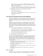
- Fault - This is the over temperature LED which illuminates red if the PSU is too hot, perhaps because of a fan tray failure. Check the fan tray LEDs on the controller card. - Over Temp - This is the DC power good LED which illuminates green if the DC output is within acceptable limits or amber if the DC output is faulty. • The QM580 clock generator box has the following status LEDs: - Pwr On, (power on) green. - Clk In OK, (clock in OK) green. - Master, amber - This LED indicates that the clock box is the master source of the signal for the network. - Error, red. 10.2 Using the Component LEDs for Fault Diagnosis The component LEDs provide a first level diagnostic for hardware problems. The following sections explain how to use the LEDs to isolate hardware faults or to determine the proper operation of hardware and thus isolate a potential software problem. Link LEDs are those that enable you to verify the status of a cable connection between one component and another, such as the QM500 PCI card in a node and the switch cards in the interconnect. A link can be node-to-interconnect, or interconnect-to-interconnect for federated configurations. Each card has a group of three red, amber, and green LEDs. Each LED has the following meaning when illuminated: • Red - An illuminated red LED has three possible interpretations - An error has been detected since the registers were last cleared. - The module is initializing or the node is rebooting and the LED will stop glowing when the process is complete (indicating a good link). - There is no link cable installed (unused port). • Amber (flashing) - Data traffic is flowing on the link. • Green - The link is connected and good. Where two functional components are powered on and connected by a functional link cable, the green LEDs are illuminated. An illuminated red LED indicates that a component or the link cable might be faulty. The fault might only be an installation problem, such as a card that is not correctly seated in the slot or a cable that is not securely seated in a port. You can use the LEDs to diagnose the network as follows: • Using LEDs to diagnose problems in the link between a node and its port on the interconnect is described in Section 10.2.1. • Using LEDs to diagnose problems in the interconnect controller card is described in Section 10.2.2. • Using LEDs to diagnose problems in the power supply unit (PSU) is described in Section 10.2.3. • Using LEDs to diagnose problems in the clock generator is described in Section 10.2.4. 10.2.1 Link LEDs Link LEDs are those that enable you to verify the status of a cable connection between one component and another, such as the QM500 PCI card in a node Using Component LEDs 10-3
-
 1
1 -
2
-
3
-
4
-
5
-
6
-
7
-
8
-
9
-
10
-
11
-
12
-
13
-
14
-
15
-
16
-
17
-
18
-
19
-
20
-
21
-
22
-
23
-
24
-
25
-
26
-
27
-
28
-
29
-
30
-
31
-
32
-
33
-
34
-
35
-
36
-
37
-
38
-
39
-
40
-
41
-
42
-
43
-
44
-
45
-
46
-
47
-
48
-
49
-
50
-
51
-
52
-
53
-
54
-
55
-
56
-
57
-
58
-
59
-
60
-
61
-
62
-
63
-
64
-
65
-
66
-
67
-
68
-
69
-
70
-
71
-
72
-
73
-
74
-
75
-
76
-
77
-
78
-
79
-
80
-
81
-
82
-
83
-
 84
84 -
 85
85 -
 86
86 -
 87
87 -
 88
88 -
 89
89 -
 90
90 -
 91
91 -
 92
92 -
 93
93 -
 94
94 -
95
-
96
-
97
-
98
-
99
-
100
-
101
-
102
-
103
-
104
-
105
-
106
-
107
-
108
-
109
-
110
-
111
-
112
-
113
-
114
-
115
-
116
-
117
-
118
-
119
-
120
-
121
-
122
-
123
-
124
-
125
-
126
-
127
-
128
-
129
-
130
-
131
-
132
-
133
-
134
-
135
-
136
-
137
-
138
-
139
-
140
-
141
-
142
-
143
-
144
-
145
-
146
-
147
-
148
-
149
-
150
-
151
-
152
-
153
-
154
-
155
-
156
-
157
-
158
-
159
-
160
-
161
-
162
-
163
-
164
-
165
-
166
 |
 |