HP Cluster Platform Interconnects v2010 Quadrics QsNetII Interconnect - Page 57
Inserting or Removing a Power Supply, Table 7-1: Table 2-3 Power Supply LEDs
 |
View all HP Cluster Platform Interconnects v2010 manuals
Add to My Manuals
Save this manual to your list of manuals |
Page 57 highlights
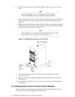
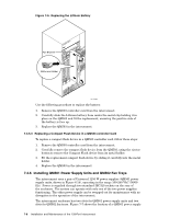
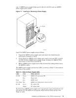
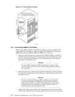
unit. A QM566 power supply blank must be fitted to slot B if only one QM561 power supply unit is fitted. Figure 7-7: Inserting or Removing a Power Supply QUaDrics QsNet" PSU A PSU B PSU A Latch HPTC-0033 Install the QM561 power supply units as follows: 1. Unpack the QM561 power supply units and remove the blank from the interconnect enclosure, if fitted. 2. If only fitting one QM561 power supply unit, insert it into slot PSU A and fit slot PSU B with a QM566 power supply blank. If fitting two QM561 PSUs, insert them in slots PSU A and PSU B. 3. When a QM561 power supply unit is fully inserted, the locking latch secures the QM561 in place. The QM561 power supply unit has four LEDs, as shown in Table 7-1 that indicate the status of the module. Table 7-1: Table 2-3 Power Supply LEDs Label Color Status when Lit AC OK Green QM561 ON and mains OK Red Mains fault Fault Red QM561 fault Over Temp Red QM561 over temperature alarm is active DC OK Green DC output OK Amber DC output fault To verify that a QM561 power supply unit is operational, ensure that both the AC OK and the DC OK LEDs are lit up green, while both the Fault and the Over Temp are unlit. Installation and Maintenance of the 128-Port Interconnect 7-9
-
 1
1 -
2
-
3
-
4
-
5
-
6
-
7
-
8
-
9
-
10
-
11
-
12
-
13
-
14
-
15
-
16
-
17
-
18
-
19
-
20
-
21
-
22
-
23
-
24
-
25
-
26
-
27
-
28
-
29
-
30
-
31
-
32
-
33
-
34
-
35
-
36
-
37
-
38
-
39
-
40
-
41
-
42
-
43
-
44
-
45
-
46
-
47
-
48
-
49
-
50
-
51
-
 52
52 -
 53
53 -
 54
54 -
 55
55 -
 56
56 -
 57
57 -
 58
58 -
 59
59 -
 60
60 -
 61
61 -
 62
62 -
63
-
64
-
65
-
66
-
67
-
68
-
69
-
70
-
71
-
72
-
73
-
74
-
75
-
76
-
77
-
78
-
79
-
80
-
81
-
82
-
83
-
84
-
85
-
86
-
87
-
88
-
89
-
90
-
91
-
92
-
93
-
94
-
95
-
96
-
97
-
98
-
99
-
100
-
101
-
102
-
103
-
104
-
105
-
106
-
107
-
108
-
109
-
110
-
111
-
112
-
113
-
114
-
115
-
116
-
117
-
118
-
119
-
120
-
121
-
122
-
123
-
124
-
125
-
126
-
127
-
128
-
129
-
130
-
131
-
132
-
133
-
134
-
135
-
136
-
137
-
138
-
139
-
140
-
141
-
142
-
143
-
144
-
145
-
146
-
147
-
148
-
149
-
150
-
151
-
152
-
153
-
154
-
155
-
156
-
157
-
158
-
159
-
160
-
161
-
162
-
163
-
164
-
165
-
166
 |
 |
