Netgear GS724TPv2 User Manual - Page 117
Con Spanning Tree Protocol, Con STP Settings
 |
View all Netgear GS724TPv2 manuals
Add to My Manuals
Save this manual to your list of manuals |
Page 117 highlights
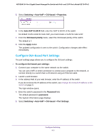
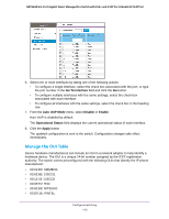
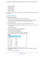
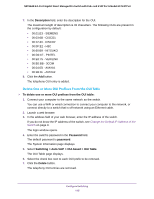
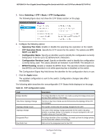
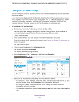
NETGEAR 24-Port Gigabit Smart Managed Pro Switch with PoE+ and 2 SFP Ports Model GS724TPv2 Configure Spanning Tree Protocol The Spanning Tree Protocol (STP) provides a tree topology for any arrangement of bridges. STP also provides one path between end stations on a network, eliminating loops. Spanning tree versions supported include Common STP, Multiple STP, and Rapid STP. Classic STP provides a single path between end stations, avoiding and eliminating loops. For information on configuring Common STP, see Configure CST Port Settings on page 121. Multiple Spanning Tree Protocol (MSTP) supports multiple instances of spanning tree to efficiently channel VLAN traffic over different interfaces. Each instance of the spanning tree behaves in the manner specified in IEEE 802.1w, Rapid Spanning Tree (RSTP), with slight modifications in the working but not the end effect (chief among the effects is the rapid transitioning of the port to the forwarding state). The difference between the RSTP and the traditional STP (IEEE 802.1D) is the ability to configure and recognize full-duplex connectivity and ports that are connected to end stations, resulting in rapid transitioning of the port to the forwarding state and the suppression of Topology Change Notification. These features are represented by the parameters pointtopoint and edgeport. MSTP is compatible with both RSTP and STP. It behaves in a way that is appropriate for STP and RSTP bridges. An MSTP bridge can be configured to behave entirely as an RSTP bridge or an STP bridge. Note: For two bridges to be in the same region, the force version must be 802.1s and their configuration names, digest keys, and revision levels must match. For additional information about regions and their effect on network topology, refer to the IEEE 802.1Q standard. Configure STP Settings The STP Configuration page contains fields for enabling STP on the switch. To configure STP settings: 1. Connect your computer to the same network as the switch. You can use a WiFi or wired connection to connect your computer to the network, or connect directly to a switch that is off-network using an Ethernet cable. 2. Launch a web browser. 3. In the address field of your web browser, enter the IP address of the switch. If you do not know the IP address of the switch, see Change the Default IP Address of the Switch on page 9. The login window opens. 4. Enter the switch's password in the Password field. The default password is password. The System Information page displays. Configure Switching 117
-
 1
1 -
2
-
3
-
4
-
5
-
6
-
7
-
8
-
9
-
10
-
11
-
12
-
13
-
14
-
15
-
16
-
17
-
18
-
19
-
20
-
21
-
22
-
23
-
24
-
25
-
26
-
27
-
28
-
29
-
30
-
31
-
32
-
33
-
34
-
35
-
36
-
37
-
38
-
39
-
40
-
41
-
42
-
43
-
44
-
45
-
46
-
47
-
48
-
49
-
50
-
51
-
52
-
53
-
54
-
55
-
56
-
57
-
58
-
59
-
60
-
61
-
62
-
63
-
64
-
65
-
66
-
67
-
68
-
69
-
70
-
71
-
72
-
73
-
74
-
75
-
76
-
77
-
78
-
79
-
80
-
81
-
82
-
83
-
84
-
85
-
86
-
87
-
88
-
89
-
90
-
91
-
92
-
93
-
94
-
95
-
96
-
97
-
98
-
99
-
100
-
101
-
102
-
103
-
104
-
105
-
106
-
107
-
108
-
109
-
110
-
111
-
 112
112 -
 113
113 -
 114
114 -
 115
115 -
 116
116 -
 117
117 -
 118
118 -
 119
119 -
 120
120 -
 121
121 -
 122
122 -
123
-
124
-
125
-
126
-
127
-
128
-
129
-
130
-
131
-
132
-
133
-
134
-
135
-
136
-
137
-
138
-
139
-
140
-
141
-
142
-
143
-
144
-
145
-
146
-
147
-
148
-
149
-
150
-
151
-
152
-
153
-
154
-
155
-
156
-
157
-
158
-
159
-
160
-
161
-
162
-
163
-
164
-
165
-
166
-
167
-
168
-
169
-
170
-
171
-
172
-
173
-
174
-
175
-
176
-
177
-
178
-
179
-
180
-
181
-
182
-
183
-
184
-
185
-
186
-
187
-
188
-
189
-
190
-
191
-
192
-
193
-
194
-
195
-
196
-
197
-
198
-
199
-
200
-
201
-
202
-
203
-
204
-
205
-
206
-
207
-
208
-
209
-
210
-
211
-
212
-
213
-
214
-
215
-
216
-
217
-
218
-
219
-
220
-
221
-
222
-
223
-
224
-
225
-
226
-
227
-
228
-
229
-
230
-
231
-
232
-
233
-
234
-
235
-
236
-
237
-
238
-
239
-
240
-
241
-
242
-
243
-
244
-
245
-
246
-
247
-
248
-
249
-
250
-
251
-
252
-
253
-
254
-
255
-
256
-
257
-
258
-
259
-
260
-
261
-
262
-
263
-
264
-
265
-
266
-
267
-
268
-
269
-
270
-
271
-
272
-
273
-
274
-
275
-
276
-
277
-
278
-
279
-
280
-
281
-
282
-
283
-
284
-
285
-
286
-
287
-
288
-
289
-
290
-
291
-
292
-
293
-
294
-
295
-
296
-
297
-
298
-
299
-
300
-
301
-
302
-
303
-
304
-
305
-
306
-
307
-
308
-
309
-
310
-
311
-
312
-
313
-
314
-
315
-
316
-
317
 |
 |