Netgear GS724TPv2 User Manual - Page 303
MSTP, Instance MSTI, within Multiple Spanning Tree MST regions composed of LANs and or
 |
View all Netgear GS724TPv2 manuals
Add to My Manuals
Save this manual to your list of manuals |
Page 303 highlights
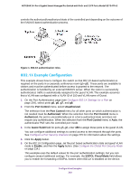
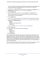
NETGEAR 24-Port Gigabit Smart Managed Pro Switch with PoE+ and 2 SFP Ports Model GS724TPv2 6. On the RADIUS Server Configuration page (see Add a Primary RADIUS Authentication Server to the Switch on page 182), configure a RADIUS server with the following settings: • Server Address. 192.168.10.23 • Secret Configured. Yes • Secret. secret123 • Active. Primary For more information, see Configure RADIUS Servers on page 180. 7. Click the Add button. 8. On the Authentication List page, configure the default list to use RADIUS as the first authentication method. (See Configure Authentication Lists on page 191.) This example enables 802.1X-based port security on the switch and prompts the hosts connected on ports g5-g8 for an 802.1X-based authentication. The switch passes the authentication information to the configured RADIUS server. MSTP Spanning Tree Protocol (STP) runs on bridged networks to help eliminate loops. If a bridge loop occurs, the network can become flooded with traffic. IEEE 802.1s Multiple Spanning Tree Protocol (MSTP) supports multiple instances of spanning tree to efficiently channel VLAN traffic over different interfaces. Each instance of the spanning tree behaves in the manner specified in IEEE 802.1w, Rapid Spanning Tree, with slight modifications in the working but not the end effect (chief among the effects is the rapid transitioning of the port to the forwarding state). The difference between the RSTP and the traditional STP (IEEE 802.1D) is the ability to configure and recognize full-duplex connectivity and ports that are connected to end stations, resulting in rapid transitioning of the port to the Forwarding state and the suppression of Topology Change Notification. These features are represented by the parameters pointtopoint and edgeport. MSTP is compatible to both RSTP and STP. It behaves in a way that is appropriate for STP and RSTP bridges. An MSTP bridge can be configured to behave entirely as a RSTP bridge or an STP bridge. So, an IEEE 802.1s bridge inherently also supports IEEE 802.1w and IEEE 802.1D. The MSTP algorithm and protocol provide simple and full connectivity for frames assigned to any given VLAN throughout a bridged LAN comprising arbitrarily interconnected networking devices, each operating MSTP, STP, or RSTP. MSTP allows frames assigned to different VLANs to follow separate paths, each based on an independent Multiple Spanning Tree Instance (MSTI), within Multiple Spanning Tree (MST) regions composed of LANs and or MSTP bridges. These regions and the other bridges and LANs are connected into a single Common Spanning Tree (CST). (IEEE DRAFT P802.1s/D13) MSTP connects all bridges and LANs with a single Common and Internal Spanning Tree (CIST). The CIST supports the automatic determination of each MST region, choosing its maximum possible extent. The connectivity calculated for the CIST provides the CST for interconnecting these regions, and an Internal Spanning Tree (IST) within each region. MSTP Configuration Examples 303
-
 1
1 -
2
-
3
-
4
-
5
-
6
-
7
-
8
-
9
-
10
-
11
-
12
-
13
-
14
-
15
-
16
-
17
-
18
-
19
-
20
-
21
-
22
-
23
-
24
-
25
-
26
-
27
-
28
-
29
-
30
-
31
-
32
-
33
-
34
-
35
-
36
-
37
-
38
-
39
-
40
-
41
-
42
-
43
-
44
-
45
-
46
-
47
-
48
-
49
-
50
-
51
-
52
-
53
-
54
-
55
-
56
-
57
-
58
-
59
-
60
-
61
-
62
-
63
-
64
-
65
-
66
-
67
-
68
-
69
-
70
-
71
-
72
-
73
-
74
-
75
-
76
-
77
-
78
-
79
-
80
-
81
-
82
-
83
-
84
-
85
-
86
-
87
-
88
-
89
-
90
-
91
-
92
-
93
-
94
-
95
-
96
-
97
-
98
-
99
-
100
-
101
-
102
-
103
-
104
-
105
-
106
-
107
-
108
-
109
-
110
-
111
-
112
-
113
-
114
-
115
-
116
-
117
-
118
-
119
-
120
-
121
-
122
-
123
-
124
-
125
-
126
-
127
-
128
-
129
-
130
-
131
-
132
-
133
-
134
-
135
-
136
-
137
-
138
-
139
-
140
-
141
-
142
-
143
-
144
-
145
-
146
-
147
-
148
-
149
-
150
-
151
-
152
-
153
-
154
-
155
-
156
-
157
-
158
-
159
-
160
-
161
-
162
-
163
-
164
-
165
-
166
-
167
-
168
-
169
-
170
-
171
-
172
-
173
-
174
-
175
-
176
-
177
-
178
-
179
-
180
-
181
-
182
-
183
-
184
-
185
-
186
-
187
-
188
-
189
-
190
-
191
-
192
-
193
-
194
-
195
-
196
-
197
-
198
-
199
-
200
-
201
-
202
-
203
-
204
-
205
-
206
-
207
-
208
-
209
-
210
-
211
-
212
-
213
-
214
-
215
-
216
-
217
-
218
-
219
-
220
-
221
-
222
-
223
-
224
-
225
-
226
-
227
-
228
-
229
-
230
-
231
-
232
-
233
-
234
-
235
-
236
-
237
-
238
-
239
-
240
-
241
-
242
-
243
-
244
-
245
-
246
-
247
-
248
-
249
-
250
-
251
-
252
-
253
-
254
-
255
-
256
-
257
-
258
-
259
-
260
-
261
-
262
-
263
-
264
-
265
-
266
-
267
-
268
-
269
-
270
-
271
-
272
-
273
-
274
-
275
-
276
-
277
-
278
-
279
-
280
-
281
-
282
-
283
-
284
-
285
-
286
-
287
-
288
-
289
-
290
-
291
-
292
-
293
-
294
-
295
-
296
-
297
-
 298
298 -
 299
299 -
 300
300 -
 301
301 -
 302
302 -
 303
303 -
 304
304 -
 305
305 -
 306
306 -
 307
307 -
 308
308 -
309
-
310
-
311
-
312
-
313
-
314
-
315
-
316
-
317
 |
 |