Netgear GS724TPv2 User Manual - Page 166
Destination IP, Address, Destination L4 Port, Other, IP DSCP, Precedence Value, IP ToS, Bits Value
 |
View all Netgear GS724TPv2 manuals
Add to My Manuals
Save this manual to your list of manuals |
Page 166 highlights
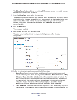
NETGEAR 24-Port Gigabit Smart Managed Pro Switch with PoE+ and 2 SFP Ports Model GS724TPv2 • Destination IP. Select this radio button to require a packet's destination IP address to match the specified IP address. After you select the radio button, use the following fields to configure the destination IP address match criteria: - Address. The destination IP address format to match in dotted-decimal. - Mask. The bit mask in IP dotted-decimal format indicating which parts of the destination IP address to use for matching against packet content. • Destination L4 Port. Select this radio button to require a packet's TCP/UDP destination port to match the specified protocol, which you must select from the menu. The menu includes Other as a selection, which lets you enter a destination port number. • IP DSCP. Select this radio button to require the packet's IP DiffServ Code Point (DSCP) value to match the specified IP DSCP keyword code, which you must select from the menu. The menu includes Other as a selection, which lets you enter an IP DSCP value from 0 to 63. The DSCP value is defined as the high-order 6 bits of the Service Type octet in the IP header. • Precedence Value. Select this radio button to require the packet's IP precedence value to match the specified number from 0 to 7, which you must select from the menu. The IP Precedence field in a packet is defined as the high-order 3 bits of the Service Type octet in the IP header. • IP ToS. Select this radio button to require the packet's Type of Service (ToS) bits in the IP header to match the specified value. The IP ToS field in a packet is defined as all 8 bits of the service type octet in the IP header. After you select the radio button, use the following fields to configure the ToS match criteria: - Bits Value. Enter a two-digit hexadecimal number octet value in the range from 00 to ff to match the bits in a packet's ToS field. - Bit Mask. Specify the bit positions that are used for comparison against the IP ToS field in a packet. 11. Click the Apply button. The updated configuration is sent to the switch. Configuration changes take effect immediately. The following table describes the nonconfigurable information on the page. Table 38. DiffServ Class Configuration, Class Summary information Field Match Criteria Values Description The configured match criteria for the specified class. The values of the configured match criteria. Configure Quality of Service 166
-
 1
1 -
2
-
3
-
4
-
5
-
6
-
7
-
8
-
9
-
10
-
11
-
12
-
13
-
14
-
15
-
16
-
17
-
18
-
19
-
20
-
21
-
22
-
23
-
24
-
25
-
26
-
27
-
28
-
29
-
30
-
31
-
32
-
33
-
34
-
35
-
36
-
37
-
38
-
39
-
40
-
41
-
42
-
43
-
44
-
45
-
46
-
47
-
48
-
49
-
50
-
51
-
52
-
53
-
54
-
55
-
56
-
57
-
58
-
59
-
60
-
61
-
62
-
63
-
64
-
65
-
66
-
67
-
68
-
69
-
70
-
71
-
72
-
73
-
74
-
75
-
76
-
77
-
78
-
79
-
80
-
81
-
82
-
83
-
84
-
85
-
86
-
87
-
88
-
89
-
90
-
91
-
92
-
93
-
94
-
95
-
96
-
97
-
98
-
99
-
100
-
101
-
102
-
103
-
104
-
105
-
106
-
107
-
108
-
109
-
110
-
111
-
112
-
113
-
114
-
115
-
116
-
117
-
118
-
119
-
120
-
121
-
122
-
123
-
124
-
125
-
126
-
127
-
128
-
129
-
130
-
131
-
132
-
133
-
134
-
135
-
136
-
137
-
138
-
139
-
140
-
141
-
142
-
143
-
144
-
145
-
146
-
147
-
148
-
149
-
150
-
151
-
152
-
153
-
154
-
155
-
156
-
157
-
158
-
159
-
160
-
 161
161 -
 162
162 -
 163
163 -
 164
164 -
 165
165 -
 166
166 -
 167
167 -
 168
168 -
 169
169 -
 170
170 -
 171
171 -
172
-
173
-
174
-
175
-
176
-
177
-
178
-
179
-
180
-
181
-
182
-
183
-
184
-
185
-
186
-
187
-
188
-
189
-
190
-
191
-
192
-
193
-
194
-
195
-
196
-
197
-
198
-
199
-
200
-
201
-
202
-
203
-
204
-
205
-
206
-
207
-
208
-
209
-
210
-
211
-
212
-
213
-
214
-
215
-
216
-
217
-
218
-
219
-
220
-
221
-
222
-
223
-
224
-
225
-
226
-
227
-
228
-
229
-
230
-
231
-
232
-
233
-
234
-
235
-
236
-
237
-
238
-
239
-
240
-
241
-
242
-
243
-
244
-
245
-
246
-
247
-
248
-
249
-
250
-
251
-
252
-
253
-
254
-
255
-
256
-
257
-
258
-
259
-
260
-
261
-
262
-
263
-
264
-
265
-
266
-
267
-
268
-
269
-
270
-
271
-
272
-
273
-
274
-
275
-
276
-
277
-
278
-
279
-
280
-
281
-
282
-
283
-
284
-
285
-
286
-
287
-
288
-
289
-
290
-
291
-
292
-
293
-
294
-
295
-
296
-
297
-
298
-
299
-
300
-
301
-
302
-
303
-
304
-
305
-
306
-
307
-
308
-
309
-
310
-
311
-
312
-
313
-
314
-
315
-
316
-
317
 |
 |