Netgear GS724TPv2 User Manual - Page 156
Con CoS Queue Settings for an Interface, Interface Trust Mode, Untrusted, Interface Shaping Rate
 |
View all Netgear GS724TPv2 manuals
Add to My Manuals
Save this manual to your list of manuals |
Page 156 highlights
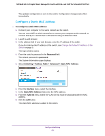
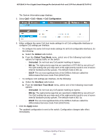
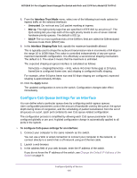
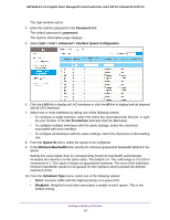
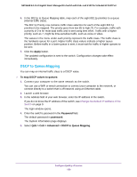
NETGEAR 24-Port Gigabit Smart Managed Pro Switch with PoE+ and 2 SFP Ports Model GS724TPv2 8. From the Interface Trust Mode menu, select one of the following trust mode options for ingress traffic on the selected interfaces: • Untrusted. Do not trust any CoS packet marking at ingress. • 802.1p. The eight priority tags that are specified in IEEE 802.1p are p0 to p7. The QoS setting lets you map each of the eight priority levels to one of seven internal hardware priority queues. The default is 802.1p. • DSCP. The six most significant bits of the DiffServ field are called the Differentiated Services Code Point (DSCP) bits. 9. In the Interface Shaping Rate field, specify the maximum bandwidth allowed. This is typically used to shape the outbound transmission rate in increments of 64 kbps in the range 16 to 16384 kbps.This value is controlled independently of any per-queue maximum bandwidth configuration. It is effectively a second-level shaping mechanism. The default is 0. The value 0 means that the maximum is unlimited. The expected shaping at egress interface is calculated as follows: frameSize × shaping/(frameSize + IFG), where IFG (Inter frame gap) is 20 bytes, frameSize is configured frame size, and shaping is configured traffic shaping. For example, when 64 bytes frame size and 64 kbps shaping are configured, expected shaping is approximately 48 kbps. 10. Click the Apply button. The updated configuration is sent to the switch. Configuration changes take effect immediately. Configure CoS Queue Settings for an Interface You can define what a particular queue does by configuring switch egress queues. User-configurable parameters control the amount of bandwidth used by the queue, the queue depth during times of congestion, and the scheduling of packet transmission from the set of all queues on a port. Each port contains its own CoS queue-related configuration. The configuration process is simplified by allowing each CoS queue parameter to be configured globally or per port. A global configuration change is automatically applied to all ports in the system. To configure CoS queue settings for an interface: 1. Connect your computer to the same network as the switch. You can use a WiFi or wired connection to connect your computer to the network, or connect directly to a switch that is off-network using an Ethernet cable. 2. Launch a web browser. 3. In the address field of your web browser, enter the IP address of the switch. If you do not know the IP address of the switch, see Change the Default IP Address of the Switch on page 9. Configure Quality of Service 156
-
 1
1 -
2
-
3
-
4
-
5
-
6
-
7
-
8
-
9
-
10
-
11
-
12
-
13
-
14
-
15
-
16
-
17
-
18
-
19
-
20
-
21
-
22
-
23
-
24
-
25
-
26
-
27
-
28
-
29
-
30
-
31
-
32
-
33
-
34
-
35
-
36
-
37
-
38
-
39
-
40
-
41
-
42
-
43
-
44
-
45
-
46
-
47
-
48
-
49
-
50
-
51
-
52
-
53
-
54
-
55
-
56
-
57
-
58
-
59
-
60
-
61
-
62
-
63
-
64
-
65
-
66
-
67
-
68
-
69
-
70
-
71
-
72
-
73
-
74
-
75
-
76
-
77
-
78
-
79
-
80
-
81
-
82
-
83
-
84
-
85
-
86
-
87
-
88
-
89
-
90
-
91
-
92
-
93
-
94
-
95
-
96
-
97
-
98
-
99
-
100
-
101
-
102
-
103
-
104
-
105
-
106
-
107
-
108
-
109
-
110
-
111
-
112
-
113
-
114
-
115
-
116
-
117
-
118
-
119
-
120
-
121
-
122
-
123
-
124
-
125
-
126
-
127
-
128
-
129
-
130
-
131
-
132
-
133
-
134
-
135
-
136
-
137
-
138
-
139
-
140
-
141
-
142
-
143
-
144
-
145
-
146
-
147
-
148
-
149
-
150
-
 151
151 -
 152
152 -
 153
153 -
 154
154 -
 155
155 -
 156
156 -
 157
157 -
 158
158 -
 159
159 -
 160
160 -
 161
161 -
162
-
163
-
164
-
165
-
166
-
167
-
168
-
169
-
170
-
171
-
172
-
173
-
174
-
175
-
176
-
177
-
178
-
179
-
180
-
181
-
182
-
183
-
184
-
185
-
186
-
187
-
188
-
189
-
190
-
191
-
192
-
193
-
194
-
195
-
196
-
197
-
198
-
199
-
200
-
201
-
202
-
203
-
204
-
205
-
206
-
207
-
208
-
209
-
210
-
211
-
212
-
213
-
214
-
215
-
216
-
217
-
218
-
219
-
220
-
221
-
222
-
223
-
224
-
225
-
226
-
227
-
228
-
229
-
230
-
231
-
232
-
233
-
234
-
235
-
236
-
237
-
238
-
239
-
240
-
241
-
242
-
243
-
244
-
245
-
246
-
247
-
248
-
249
-
250
-
251
-
252
-
253
-
254
-
255
-
256
-
257
-
258
-
259
-
260
-
261
-
262
-
263
-
264
-
265
-
266
-
267
-
268
-
269
-
270
-
271
-
272
-
273
-
274
-
275
-
276
-
277
-
278
-
279
-
280
-
281
-
282
-
283
-
284
-
285
-
286
-
287
-
288
-
289
-
290
-
291
-
292
-
293
-
294
-
295
-
296
-
297
-
298
-
299
-
300
-
301
-
302
-
303
-
304
-
305
-
306
-
307
-
308
-
309
-
310
-
311
-
312
-
313
-
314
-
315
-
316
-
317
 |
 |
