Netgear GS724TPv2 User Manual - Page 306
Enable, STP Status, Apply, Fast Link, MST ID, Priority, VLAN ID, Con CST Settings
 |
View all Netgear GS724TPv2 manuals
Add to My Manuals
Save this manual to your list of manuals |
Page 306 highlights
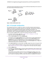
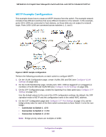
NETGEAR 24-Port Gigabit Smart Managed Pro Switch with PoE+ and 2 SFP Ports Model GS724TPv2 If you do not specify a root bridge and all switches are assigned the same bridge priority value, the switch with the lowest MAC address is elected as the root bridge (see Configure CST Settings on page 119). 5. On the CST Port Configuration page, select ports 1/0/1-1/0/8 and select Enable from the STP Status menu (see Configure CST Port Settings on page 121). 6. Click the Apply button. 7. Select ports 1/0/1-1/0/5 (edge ports), and select Enable from the Fast Link menu. Since the edge ports are not at risk for network loops, ports with Fast Link enabled transition directly to the forwarding state. 8. Click the Apply button. On the CST Port Status page you can view spanning tree information about each port. 9. On the MST Configuration page (see Manage MST Settings on page 125), create a MST instances with the following settings: • MST ID. 1 • Priority. Use the default (32768) • VLAN ID. 300 For more information, see View Rapid STP Information on page 124. 10. Click the Add button. 11. Create a second MST instance with the following settings • MST ID. 2 • Priority. 49152 • VLAN ID. 500 12. Click the Add button. In this example, assume that Switch 1 became the root bridge for the MST instance 1, and Switch 2 became the root bridge for MST instance 2. Switch 3 supports hosts in the sales department (ports 1/0/1, 1/0/2, and 1/0/3) and in the HR department (ports 1/0/4 and 1/0/5). Switches 1 and 2 also include hosts in the sales and HR departments. The hosts connected from Switch 2 use VLAN 500, MST instance 2 to communicate with the hosts on Switch 3 directly. Likewise, hosts of Switch 1 use VLAN 300, MST instance 1 to communicate with the hosts on Switch 3 directly. The hosts use different instances of MSTP to effectively use the links across the switch. The same concept can be extended to other switches and more instances of MSTP. Configuration Examples 306
-
 1
1 -
2
-
3
-
4
-
5
-
6
-
7
-
8
-
9
-
10
-
11
-
12
-
13
-
14
-
15
-
16
-
17
-
18
-
19
-
20
-
21
-
22
-
23
-
24
-
25
-
26
-
27
-
28
-
29
-
30
-
31
-
32
-
33
-
34
-
35
-
36
-
37
-
38
-
39
-
40
-
41
-
42
-
43
-
44
-
45
-
46
-
47
-
48
-
49
-
50
-
51
-
52
-
53
-
54
-
55
-
56
-
57
-
58
-
59
-
60
-
61
-
62
-
63
-
64
-
65
-
66
-
67
-
68
-
69
-
70
-
71
-
72
-
73
-
74
-
75
-
76
-
77
-
78
-
79
-
80
-
81
-
82
-
83
-
84
-
85
-
86
-
87
-
88
-
89
-
90
-
91
-
92
-
93
-
94
-
95
-
96
-
97
-
98
-
99
-
100
-
101
-
102
-
103
-
104
-
105
-
106
-
107
-
108
-
109
-
110
-
111
-
112
-
113
-
114
-
115
-
116
-
117
-
118
-
119
-
120
-
121
-
122
-
123
-
124
-
125
-
126
-
127
-
128
-
129
-
130
-
131
-
132
-
133
-
134
-
135
-
136
-
137
-
138
-
139
-
140
-
141
-
142
-
143
-
144
-
145
-
146
-
147
-
148
-
149
-
150
-
151
-
152
-
153
-
154
-
155
-
156
-
157
-
158
-
159
-
160
-
161
-
162
-
163
-
164
-
165
-
166
-
167
-
168
-
169
-
170
-
171
-
172
-
173
-
174
-
175
-
176
-
177
-
178
-
179
-
180
-
181
-
182
-
183
-
184
-
185
-
186
-
187
-
188
-
189
-
190
-
191
-
192
-
193
-
194
-
195
-
196
-
197
-
198
-
199
-
200
-
201
-
202
-
203
-
204
-
205
-
206
-
207
-
208
-
209
-
210
-
211
-
212
-
213
-
214
-
215
-
216
-
217
-
218
-
219
-
220
-
221
-
222
-
223
-
224
-
225
-
226
-
227
-
228
-
229
-
230
-
231
-
232
-
233
-
234
-
235
-
236
-
237
-
238
-
239
-
240
-
241
-
242
-
243
-
244
-
245
-
246
-
247
-
248
-
249
-
250
-
251
-
252
-
253
-
254
-
255
-
256
-
257
-
258
-
259
-
260
-
261
-
262
-
263
-
264
-
265
-
266
-
267
-
268
-
269
-
270
-
271
-
272
-
273
-
274
-
275
-
276
-
277
-
278
-
279
-
280
-
281
-
282
-
283
-
284
-
285
-
286
-
287
-
288
-
289
-
290
-
291
-
292
-
293
-
294
-
295
-
296
-
297
-
298
-
299
-
300
-
 301
301 -
 302
302 -
 303
303 -
 304
304 -
 305
305 -
 306
306 -
 307
307 -
 308
308 -
 309
309 -
 310
310 -
 311
311 -
312
-
313
-
314
-
315
-
316
-
317
 |
 |
