Netgear GS724TPv2 User Manual - Page 304
Configuration Table a VLAN ID to MSTID mapping
 |
View all Netgear GS724TPv2 manuals
Add to My Manuals
Save this manual to your list of manuals |
Page 304 highlights
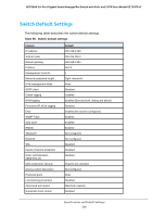
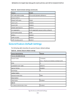
NETGEAR 24-Port Gigabit Smart Managed Pro Switch with PoE+ and 2 SFP Ports Model GS724TPv2 ensures that frames with a given VLAN ID are assigned to one and only one of the MSTIs or the IST within the region, that the assignment is consistent among all the networking devices in the region, and that the stable connectivity of each MSTI and IST at the boundary of the region matches that of the CST. The stable active topology of the bridged LAN with respect to frames consistently classified as belonging to any given VLAN thus simply and fully connects all LANs and networking devices throughout the network, though frames belonging to different VLANs can take different paths within any region, per IEEE DRAFT P802.1s/D13. All bridges, whether they use STP, RSTP, or MSTP, send information in configuration messages through Bridge Protocol Data Units (BPDUs) to assign port roles that determine each port's participation in a fully and simply connected active topology based on one or more spanning trees. The information communicated is known as the spanning tree priority vector. The BPDU structure for each of these different protocols is different. An MSTP bridge transmits the appropriate BPDU depending on the received type of BPDU from a particular port. An MST region comprises of one or more MSTP bridges with the same MST configuration identifier, using the same MSTIs, and without any bridges attached that cannot receive and transmit MSTP BPDUs. The MST configuration identifier includes the following components: 1. Configuration identifier format selector 2. Configuration name 3. Configuration revision level 4. Configuration digest: 16-byte signature of type HMAC-MD5 created from the MST Configuration Table (a VLAN ID to MSTID mapping) Because multiple instances of spanning tree exist, an MSTP state is maintained on a per-port, per-instance basis (or on a per-port, per-VLAN basis, as any VLAN can be in one and only one MSTI or CIST). For example, port A can be forwarding for instance 1 while discarding for instance 2. The port states changed since IEEE 802.1D specification. To support multiple spanning trees, configure an MSTP bridge with an unambiguous assignment of VLAN IDs (VIDs) to spanning trees. For such a configuration, ensure the following: 1. The allocation of VIDs to FIDs is unambiguous. 2. Each FID that is supported by the bridge is allocated to exactly one spanning tree instance. The combination of VID to FID and then FID to MSTI allocation defines a mapping of VIDs to spanning tree instances, represented by the MST Configuration Table. With this allocation we ensure that every VLAN is assigned to one and only one MSTI. The CIST is also an instance of spanning tree with an MSTID of 0. VIDs might be not be allocated to an instance, but every VLAN must be allocated to one of the other instances of spanning tree. The portion of the active topology of the network that connects any two bridges in the same MST region traverses only MST bridges and LANs in that region, and never bridges of any kind outside the region. In other words, connectivity within the region is independent of external connectivity. Configuration Examples 304
-
 1
1 -
2
-
3
-
4
-
5
-
6
-
7
-
8
-
9
-
10
-
11
-
12
-
13
-
14
-
15
-
16
-
17
-
18
-
19
-
20
-
21
-
22
-
23
-
24
-
25
-
26
-
27
-
28
-
29
-
30
-
31
-
32
-
33
-
34
-
35
-
36
-
37
-
38
-
39
-
40
-
41
-
42
-
43
-
44
-
45
-
46
-
47
-
48
-
49
-
50
-
51
-
52
-
53
-
54
-
55
-
56
-
57
-
58
-
59
-
60
-
61
-
62
-
63
-
64
-
65
-
66
-
67
-
68
-
69
-
70
-
71
-
72
-
73
-
74
-
75
-
76
-
77
-
78
-
79
-
80
-
81
-
82
-
83
-
84
-
85
-
86
-
87
-
88
-
89
-
90
-
91
-
92
-
93
-
94
-
95
-
96
-
97
-
98
-
99
-
100
-
101
-
102
-
103
-
104
-
105
-
106
-
107
-
108
-
109
-
110
-
111
-
112
-
113
-
114
-
115
-
116
-
117
-
118
-
119
-
120
-
121
-
122
-
123
-
124
-
125
-
126
-
127
-
128
-
129
-
130
-
131
-
132
-
133
-
134
-
135
-
136
-
137
-
138
-
139
-
140
-
141
-
142
-
143
-
144
-
145
-
146
-
147
-
148
-
149
-
150
-
151
-
152
-
153
-
154
-
155
-
156
-
157
-
158
-
159
-
160
-
161
-
162
-
163
-
164
-
165
-
166
-
167
-
168
-
169
-
170
-
171
-
172
-
173
-
174
-
175
-
176
-
177
-
178
-
179
-
180
-
181
-
182
-
183
-
184
-
185
-
186
-
187
-
188
-
189
-
190
-
191
-
192
-
193
-
194
-
195
-
196
-
197
-
198
-
199
-
200
-
201
-
202
-
203
-
204
-
205
-
206
-
207
-
208
-
209
-
210
-
211
-
212
-
213
-
214
-
215
-
216
-
217
-
218
-
219
-
220
-
221
-
222
-
223
-
224
-
225
-
226
-
227
-
228
-
229
-
230
-
231
-
232
-
233
-
234
-
235
-
236
-
237
-
238
-
239
-
240
-
241
-
242
-
243
-
244
-
245
-
246
-
247
-
248
-
249
-
250
-
251
-
252
-
253
-
254
-
255
-
256
-
257
-
258
-
259
-
260
-
261
-
262
-
263
-
264
-
265
-
266
-
267
-
268
-
269
-
270
-
271
-
272
-
273
-
274
-
275
-
276
-
277
-
278
-
279
-
280
-
281
-
282
-
283
-
284
-
285
-
286
-
287
-
288
-
289
-
290
-
291
-
292
-
293
-
294
-
295
-
296
-
297
-
298
-
 299
299 -
 300
300 -
 301
301 -
 302
302 -
 303
303 -
 304
304 -
 305
305 -
 306
306 -
 307
307 -
 308
308 -
 309
309 -
310
-
311
-
312
-
313
-
314
-
315
-
316
-
317
 |
 |