Netgear GS724TPv2 User Manual - Page 139
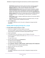
Modify IGMP Snooping Settings for a VLAN
 |
View all Netgear GS724TPv2 manuals
Add to My Manuals
Save this manual to your list of manuals |
Page 139 highlights
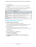
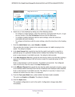
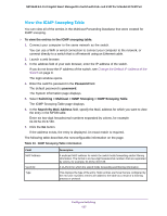
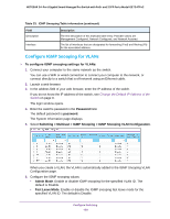
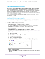
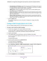
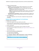
NETGEAR 24-Port Gigabit Smart Managed Pro Switch with PoE+ and 2 SFP Ports Model GS724TPv2 • Host Timeout. Specify the time that the switch must wait for a report for a particular group for the specified VLAN ID. The valid range is the value in the Maximum Response Time plus 1 to 3600 seconds. The default is 260 seconds. • Maximum Response Time. Specify the time that the switch must wait after sending a query for the specified VLAN ID if the switch does not receive a report for a particular group for that VLAN ID. Enter a value between 1 and 25 seconds. The default is 10 seconds. The configured value must be less than the value in the Host Timeout field. • MRouter Timeout. Set the value for multicast router expiry time of IGMP snooping for the specified VLAN ID. The valid range is 0 to 3600 seconds. The default is 0 seconds. • Querier Mode. Enable or disable the IGMP Querier Mode for the specified VLAN ID. The default is Disable. • Query Interval. Set the IGMP query interval for the specified VLAN ID. The valid range is 1 to 1800 seconds. The default is 60 seconds. 7. Click the Apply button. The updated configuration is sent to the switch. Configuration changes take effect immediately. Modify IGMP Snooping Settings for a VLAN To modify IGMP snooping settings for a VLAN: 1. Connect your computer to the same network as the switch. You can use a WiFi or wired connection to connect your computer to the network, or connect directly to a switch that is off-network using an Ethernet cable. 2. Launch a web browser. 3. In the address field of your web browser, enter the IP address of the switch. If you do not know the IP address of the switch, see Change the Default IP Address of the Switch on page 9. The login window opens. 4. Enter the switch's password in the Password field. The default password is password. The System Information page displays. 5. Select Switching > Multicast > IGMP Snooping > IGMP Snooping VLAN Configuration. The IGMP Snooping VLAN Configuration page displays. 6. Select the check box next to the VLAN ID. 7. Update the values. 8. Click the Apply button. The updated configuration is sent to the switch. Configuration changes take effect immediately. Configure Switching 139
-
 1
1 -
2
-
3
-
4
-
5
-
6
-
7
-
8
-
9
-
10
-
11
-
12
-
13
-
14
-
15
-
16
-
17
-
18
-
19
-
20
-
21
-
22
-
23
-
24
-
25
-
26
-
27
-
28
-
29
-
30
-
31
-
32
-
33
-
34
-
35
-
36
-
37
-
38
-
39
-
40
-
41
-
42
-
43
-
44
-
45
-
46
-
47
-
48
-
49
-
50
-
51
-
52
-
53
-
54
-
55
-
56
-
57
-
58
-
59
-
60
-
61
-
62
-
63
-
64
-
65
-
66
-
67
-
68
-
69
-
70
-
71
-
72
-
73
-
74
-
75
-
76
-
77
-
78
-
79
-
80
-
81
-
82
-
83
-
84
-
85
-
86
-
87
-
88
-
89
-
90
-
91
-
92
-
93
-
94
-
95
-
96
-
97
-
98
-
99
-
100
-
101
-
102
-
103
-
104
-
105
-
106
-
107
-
108
-
109
-
110
-
111
-
112
-
113
-
114
-
115
-
116
-
117
-
118
-
119
-
120
-
121
-
122
-
123
-
124
-
125
-
126
-
127
-
128
-
129
-
130
-
131
-
132
-
133
-
 134
134 -
 135
135 -
 136
136 -
 137
137 -
 138
138 -
 139
139 -
 140
140 -
 141
141 -
 142
142 -
 143
143 -
 144
144 -
145
-
146
-
147
-
148
-
149
-
150
-
151
-
152
-
153
-
154
-
155
-
156
-
157
-
158
-
159
-
160
-
161
-
162
-
163
-
164
-
165
-
166
-
167
-
168
-
169
-
170
-
171
-
172
-
173
-
174
-
175
-
176
-
177
-
178
-
179
-
180
-
181
-
182
-
183
-
184
-
185
-
186
-
187
-
188
-
189
-
190
-
191
-
192
-
193
-
194
-
195
-
196
-
197
-
198
-
199
-
200
-
201
-
202
-
203
-
204
-
205
-
206
-
207
-
208
-
209
-
210
-
211
-
212
-
213
-
214
-
215
-
216
-
217
-
218
-
219
-
220
-
221
-
222
-
223
-
224
-
225
-
226
-
227
-
228
-
229
-
230
-
231
-
232
-
233
-
234
-
235
-
236
-
237
-
238
-
239
-
240
-
241
-
242
-
243
-
244
-
245
-
246
-
247
-
248
-
249
-
250
-
251
-
252
-
253
-
254
-
255
-
256
-
257
-
258
-
259
-
260
-
261
-
262
-
263
-
264
-
265
-
266
-
267
-
268
-
269
-
270
-
271
-
272
-
273
-
274
-
275
-
276
-
277
-
278
-
279
-
280
-
281
-
282
-
283
-
284
-
285
-
286
-
287
-
288
-
289
-
290
-
291
-
292
-
293
-
294
-
295
-
296
-
297
-
298
-
299
-
300
-
301
-
302
-
303
-
304
-
305
-
306
-
307
-
308
-
309
-
310
-
311
-
312
-
313
-
314
-
315
-
316
-
317
 |
 |