Netgear GS724TPv2 User Manual - Page 256
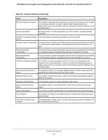
Table 54., Detailed port statistics continued, Enable, Disable, Field, Description
 |
View all Netgear GS724TPv2 manuals
Add to My Manuals
Save this manual to your list of manuals |
Page 256 highlights
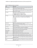
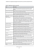
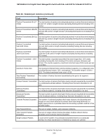
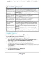
NETGEAR 24-Port Gigabit Smart Managed Pro Switch with PoE+ and 2 SFP Ports Model GS724TPv2 Table 54. Detailed port statistics (continued) Field Description Port Channel ID If the port is a member of a port channel, the port channel's interface ID and name are shown. Otherwise, Disable is shown. Port Role Each MST bridge port that is enabled is assigned a port role for each spanning tree. The port role is one of the following values: Root, Designated, Alternate, Backup, Master, or Disabled. STP Mode The Spanning Tree Protocol administrative mode associated with the port or port channel. The possible values are as follows: • Enable. Spanning tree is enabled for this port. • Disable. Spanning tree is disabled for this port. STP State The port's current Spanning Tree state. This state controls what action a port takes on receipt of a frame. If the bridge detects a malfunctioning port, it places that port into the broken state. The states are defined in IEEE 802.1D: • Disabled • Blocking • Listening • Learning • Forwarding • Broken Admin Mode The port control administration state. The port must be enabled for it to be allowed into the network. The default is Enabled. Flow Control Mode Indicates whether flow control is enabled or disabled for the port. This field is not valid for LAG interfaces. LACP Mode Indicates the Link Aggregation Control Protocol administrative state. The mode must be enabled for the port to participate in link aggregation. Physical Mode Indicates the port speed and duplex mode. In autonegotiation mode the duplex mode and speed are set from the autonegotiation process. Physical Status Indicates the port speed and duplex mode. Link Status Indicates whether the link is up or down. Link Trap Indicates whether the port sends a trap when link status changes. Packets RX and TX 64 Octets The total number of packets (including bad packets) received or transmitted that were 64 octets in length (excluding framing bits but including FCS octets). Packets RX and TX 65-127 Octets The total number of packets (including bad packets) received or transmitted that were between 65 and 127 octets in length inclusive (excluding framing bits but including FCS octets). Packets RX and TX 128-255 The total number of packets (including bad packets) received or transmitted that Octets were between 128 and 255 octets in length inclusive (excluding framing bits but including FCS octets). Monitor the System 256
-
 1
1 -
2
-
3
-
4
-
5
-
6
-
7
-
8
-
9
-
10
-
11
-
12
-
13
-
14
-
15
-
16
-
17
-
18
-
19
-
20
-
21
-
22
-
23
-
24
-
25
-
26
-
27
-
28
-
29
-
30
-
31
-
32
-
33
-
34
-
35
-
36
-
37
-
38
-
39
-
40
-
41
-
42
-
43
-
44
-
45
-
46
-
47
-
48
-
49
-
50
-
51
-
52
-
53
-
54
-
55
-
56
-
57
-
58
-
59
-
60
-
61
-
62
-
63
-
64
-
65
-
66
-
67
-
68
-
69
-
70
-
71
-
72
-
73
-
74
-
75
-
76
-
77
-
78
-
79
-
80
-
81
-
82
-
83
-
84
-
85
-
86
-
87
-
88
-
89
-
90
-
91
-
92
-
93
-
94
-
95
-
96
-
97
-
98
-
99
-
100
-
101
-
102
-
103
-
104
-
105
-
106
-
107
-
108
-
109
-
110
-
111
-
112
-
113
-
114
-
115
-
116
-
117
-
118
-
119
-
120
-
121
-
122
-
123
-
124
-
125
-
126
-
127
-
128
-
129
-
130
-
131
-
132
-
133
-
134
-
135
-
136
-
137
-
138
-
139
-
140
-
141
-
142
-
143
-
144
-
145
-
146
-
147
-
148
-
149
-
150
-
151
-
152
-
153
-
154
-
155
-
156
-
157
-
158
-
159
-
160
-
161
-
162
-
163
-
164
-
165
-
166
-
167
-
168
-
169
-
170
-
171
-
172
-
173
-
174
-
175
-
176
-
177
-
178
-
179
-
180
-
181
-
182
-
183
-
184
-
185
-
186
-
187
-
188
-
189
-
190
-
191
-
192
-
193
-
194
-
195
-
196
-
197
-
198
-
199
-
200
-
201
-
202
-
203
-
204
-
205
-
206
-
207
-
208
-
209
-
210
-
211
-
212
-
213
-
214
-
215
-
216
-
217
-
218
-
219
-
220
-
221
-
222
-
223
-
224
-
225
-
226
-
227
-
228
-
229
-
230
-
231
-
232
-
233
-
234
-
235
-
236
-
237
-
238
-
239
-
240
-
241
-
242
-
243
-
244
-
245
-
246
-
247
-
248
-
249
-
250
-
 251
251 -
 252
252 -
 253
253 -
 254
254 -
 255
255 -
 256
256 -
 257
257 -
 258
258 -
 259
259 -
 260
260 -
 261
261 -
262
-
263
-
264
-
265
-
266
-
267
-
268
-
269
-
270
-
271
-
272
-
273
-
274
-
275
-
276
-
277
-
278
-
279
-
280
-
281
-
282
-
283
-
284
-
285
-
286
-
287
-
288
-
289
-
290
-
291
-
292
-
293
-
294
-
295
-
296
-
297
-
298
-
299
-
300
-
301
-
302
-
303
-
304
-
305
-
306
-
307
-
308
-
309
-
310
-
311
-
312
-
313
-
314
-
315
-
316
-
317
 |
 |