Netgear GS724TPv2 User Manual - Page 143
Con a Static Multicast Group, Password
 |
View all Netgear GS724TPv2 manuals
Add to My Manuals
Save this manual to your list of manuals |
Page 143 highlights
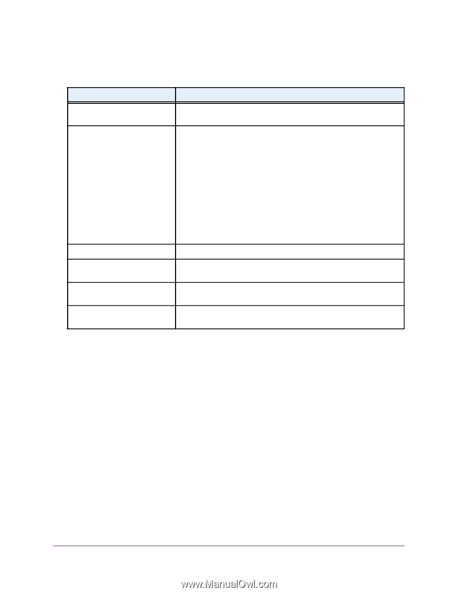
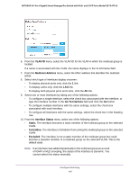
NETGEAR 24-Port Gigabit Smart Managed Pro Switch with PoE+ and 2 SFP Ports Model GS724TPv2 The following table describes the nonconfigurable information on the page. Table 34. Querier VLAN Status information Field Description VLAN ID The VLAN ID on which IGMP snooping querier is administratively enabled and the VLAN exists in the VLAN database. Operational State The operational state of the IGMP snooping querier on a VLAN. It can be in any of the following states: • Querier. The snooping switch is the querier in the VLAN. The snooping switch sends out periodic queries with a time interval equal to the configured querier query interval. If the snooping switch finds a better querier in the VLAN, it moves to non-querier mode. • Non-Querier. The snooping switch is in non-querier mode in the VLAN. If the querier expiry interval timer expires, the snooping switch moves into querier mode. • Disabled. The snooping querier is not operational on the VLAN. The snooping querier moves to disabled mode when IGMP snooping is not operational on the VLAN or when the querier address is not configured or the network management address is also not configured. Operational Version The operational IGMP protocol version of the querier. Last Querier Address The IP address of the last querier from which a query was snooped on the VLAN. Last Querier Version The IGMP protocol version of the last querier from which a query was snooped on the VLAN. Operational Max Response Time Displays maximum response time to be used in the queries that are sent by the snooping querier. Configure a Static Multicast Group You can configure up to 32 static multicast groups. You create a static multicast group by adding a multicast MAC address to a VLAN. The multicast MAC address becomes the group identifier. To configure a static multicast group: 1. Connect your computer to the same network as the switch. You can use a WiFi or wired connection to connect your computer to the network, or connect directly to a switch that is off-network using an Ethernet cable. 2. Launch a web browser. 3. In the address field of your web browser, enter the IP address of the switch. If you do not know the IP address of the switch, see Change the Default IP Address of the Switch on page 9. The login window opens. 4. Enter the switch's password in the Password field. Configure Switching 143
-
 1
1 -
2
-
3
-
4
-
5
-
6
-
7
-
8
-
9
-
10
-
11
-
12
-
13
-
14
-
15
-
16
-
17
-
18
-
19
-
20
-
21
-
22
-
23
-
24
-
25
-
26
-
27
-
28
-
29
-
30
-
31
-
32
-
33
-
34
-
35
-
36
-
37
-
38
-
39
-
40
-
41
-
42
-
43
-
44
-
45
-
46
-
47
-
48
-
49
-
50
-
51
-
52
-
53
-
54
-
55
-
56
-
57
-
58
-
59
-
60
-
61
-
62
-
63
-
64
-
65
-
66
-
67
-
68
-
69
-
70
-
71
-
72
-
73
-
74
-
75
-
76
-
77
-
78
-
79
-
80
-
81
-
82
-
83
-
84
-
85
-
86
-
87
-
88
-
89
-
90
-
91
-
92
-
93
-
94
-
95
-
96
-
97
-
98
-
99
-
100
-
101
-
102
-
103
-
104
-
105
-
106
-
107
-
108
-
109
-
110
-
111
-
112
-
113
-
114
-
115
-
116
-
117
-
118
-
119
-
120
-
121
-
122
-
123
-
124
-
125
-
126
-
127
-
128
-
129
-
130
-
131
-
132
-
133
-
134
-
135
-
136
-
137
-
 138
138 -
 139
139 -
 140
140 -
 141
141 -
 142
142 -
 143
143 -
 144
144 -
 145
145 -
 146
146 -
 147
147 -
 148
148 -
149
-
150
-
151
-
152
-
153
-
154
-
155
-
156
-
157
-
158
-
159
-
160
-
161
-
162
-
163
-
164
-
165
-
166
-
167
-
168
-
169
-
170
-
171
-
172
-
173
-
174
-
175
-
176
-
177
-
178
-
179
-
180
-
181
-
182
-
183
-
184
-
185
-
186
-
187
-
188
-
189
-
190
-
191
-
192
-
193
-
194
-
195
-
196
-
197
-
198
-
199
-
200
-
201
-
202
-
203
-
204
-
205
-
206
-
207
-
208
-
209
-
210
-
211
-
212
-
213
-
214
-
215
-
216
-
217
-
218
-
219
-
220
-
221
-
222
-
223
-
224
-
225
-
226
-
227
-
228
-
229
-
230
-
231
-
232
-
233
-
234
-
235
-
236
-
237
-
238
-
239
-
240
-
241
-
242
-
243
-
244
-
245
-
246
-
247
-
248
-
249
-
250
-
251
-
252
-
253
-
254
-
255
-
256
-
257
-
258
-
259
-
260
-
261
-
262
-
263
-
264
-
265
-
266
-
267
-
268
-
269
-
270
-
271
-
272
-
273
-
274
-
275
-
276
-
277
-
278
-
279
-
280
-
281
-
282
-
283
-
284
-
285
-
286
-
287
-
288
-
289
-
290
-
291
-
292
-
293
-
294
-
295
-
296
-
297
-
298
-
299
-
300
-
301
-
302
-
303
-
304
-
305
-
306
-
307
-
308
-
309
-
310
-
311
-
312
-
313
-
314
-
315
-
316
-
317
 |
 |