Yamaha QL5 Reference Manual - Page 102
Fader level and meter display, METERING POINT field, PEAK HOLD button, For INPUT METER
 |
View all Yamaha QL5 manuals
Add to My Manuals
Save this manual to your list of manuals |
Page 102 highlights
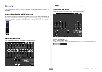
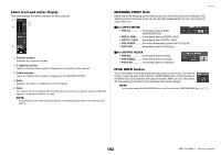
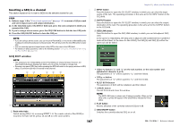
Fader level and meter display This area displays the meter and fader for each channel. 1 2 4 3 5 1 Channel number Indicates the channel number. 2 Σ clipping indicator Lights to indicate that a signal is clipping at some point in the channel. 3 OVER indicator Lights to indicate that a signal is clipping at the METERING POINT. 4 Meter Indicates the input or output level of the channel. 5 Fader The channel level is indicated by the fader position and by a numeric value (in dB) that appears immediately below the fader. NOTE Press any part of the meter area to assign the corresponding fader bank to the Channel Strip section. Meters METERING POINT field Select one of the following as the metering point at which the level will be detected. The metering point for the level meter can be specified independently for input channels and output channels. For INPUT METER • PRE GC Immediately before GAIN COMPENSATION • PRE D. GAIN .........Immediately before DIGITAL GAIN • POST D. GAIN .......Immediately after DIGITAL GAIN • PRE FADER...........Pre-fader (immediately before INPUT DELAY) • POST ON immediately after the [ON] key For OUTPUT METER • PRE EQ Immediately before the EQ • PRE FADER...........Immediately before the fader • POST ON immediately after the [ON] key PEAK HOLD button Turn on this button to hold the peak level indication on each meter. Turn off this button to clear the peak hold indication. PEAK HOLD button on/off operations will affect both input channels and output channels. When you turn this button off, the peak level indications that had been held will be cleared. NOTE You can also assign the PEAK HOLD button on/off function to a USER DEFINED key (page 169). 102 Reference Manual
-
 1
1 -
2
-
3
-
4
-
5
-
6
-
7
-
8
-
9
-
10
-
11
-
12
-
13
-
14
-
15
-
16
-
17
-
18
-
19
-
20
-
21
-
22
-
23
-
24
-
25
-
26
-
27
-
28
-
29
-
30
-
31
-
32
-
33
-
34
-
35
-
36
-
37
-
38
-
39
-
40
-
41
-
42
-
43
-
44
-
45
-
46
-
47
-
48
-
49
-
50
-
51
-
52
-
53
-
54
-
55
-
56
-
57
-
58
-
59
-
60
-
61
-
62
-
63
-
64
-
65
-
66
-
67
-
68
-
69
-
70
-
71
-
72
-
73
-
74
-
75
-
76
-
77
-
78
-
79
-
80
-
81
-
82
-
83
-
84
-
85
-
86
-
87
-
88
-
89
-
90
-
91
-
92
-
93
-
94
-
95
-
96
-
 97
97 -
 98
98 -
 99
99 -
 100
100 -
 101
101 -
 102
102 -
 103
103 -
 104
104 -
 105
105 -
 106
106 -
 107
107 -
108
-
109
-
110
-
111
-
112
-
113
-
114
-
115
-
116
-
117
-
118
-
119
-
120
-
121
-
122
-
123
-
124
-
125
-
126
-
127
-
128
-
129
-
130
-
131
-
132
-
133
-
134
-
135
-
136
-
137
-
138
-
139
-
140
-
141
-
142
-
143
-
144
-
145
-
146
-
147
-
148
-
149
-
150
-
151
-
152
-
153
-
154
-
155
-
156
-
157
-
158
-
159
-
160
-
161
-
162
-
163
-
164
-
165
-
166
-
167
-
168
-
169
-
170
-
171
-
172
-
173
-
174
-
175
-
176
-
177
-
178
-
179
-
180
-
181
-
182
-
183
-
184
-
185
-
186
-
187
-
188
-
189
-
190
-
191
-
192
-
193
-
194
-
195
-
196
-
197
-
198
-
199
-
200
-
201
-
202
-
203
-
204
-
205
-
206
-
207
-
208
-
209
-
210
-
211
-
212
-
213
-
214
-
215
-
216
-
217
-
218
-
219
-
220
-
221
-
222
-
223
-
224
-
225
-
226
-
227
-
228
-
229
-
230
-
231
-
232
-
233
-
234
-
235
-
236
-
237
-
238
-
239
-
240
-
241
-
242
-
243
-
244
-
245
-
246
-
247
-
248
-
249
-
250
-
251
-
252
-
253
-
254
-
255
-
256
-
257
-
258
-
259
-
260
-
261
-
262
-
263
-
264
 |
 |
