Yamaha QL5 Reference Manual - Page 43
TO STEREO/MONO window, CH1-32, CH33-64/ST IN QL5, ST IN QL1, OUTPUT, MODE select button
 |
View all Yamaha QL5 manuals
Add to My Manuals
Save this manual to your list of manuals |
Page 43 highlights
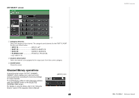
3 MODE select button Press this button repeatedly to toggle between ST/MONO and LCR. 4 ST/MONO buttons These buttons are individual on/off switches for signals that are sent from each channel to the STEREO bus/MONO bus when the MONO button is set to ST/MONO mode. 5 Σ clipping indicator Lights to indicate a signal is clipping at some point in the channel. 6 TO ST PAN/TO ST BALANCE knob If the type of the MIX channel signal is MONO, this knob will function as a PAN knob that adjusts the left and right pan position of the signal sent to the STEREO bus. If the type of MIX channel signal is STEREO, this knob will function as a BALANCE knob that adjusts the volume level balance of left and right signals sent to the STEREO bus. To adjust the value, press the knob to select it, and then operate the [TOUCH AND TURN] knob. 7 Tabs Enable you to switch between windows. 8 LCR button This button is an overall on/off button for signals sent from a channel to the STEREO bus and MONO bus. If this button is off, no signals will be sent from the corresponding input channel to the STEREO bus or MONO bus. 9 CSR knob Adjusts the relative level of signals sent from the channel to the STEREO (L/R) bus and to the MONO (C) bus, in the range of 0-100%. To adjust the value, press the knob to select it, and then operate the [TOUCH AND TURN] knob. OUTPUT channels TO STEREO/MONO window (CH1-32, CH33-64/ST IN (QL5), ST IN (QL1), OUTPUT) This window shows the status of signals sent from the corresponding channel to the STEREO bus/MONO bus. You can also adjust the selected pan or balance setting. 21 3 4 1 Channel select button Selects the channel. You can select multiple channels simultaneously. 2 Σ clipping indicator Lights to indicate a signal is clipping at some point in the channel. 3 TO ST PAN/TO ST BALANCE knob Adjusts the panning or balance. To adjust the value, press the knob to select it, and then operate the [TOUCH AND TURN] knob. If the signal level reaches the overload point at any meter detection point in that channel, the Σ clipping indicator to the right of the knob will light. 4 ST/MONO indicator If a channel is set to ST/MONO mode, these indicators will individually indicate the on/ off status of signals sent from the channel to the STEREO bus/MONO bus. If that channel is set to LCR mode, the LCR indicator will be displayed in this location. The LCR indicator indicates the on/off status of all signals sent from that channel to the STEREO bus/MONO bus. 43 Reference Manual
-
 1
1 -
2
-
3
-
4
-
5
-
6
-
7
-
8
-
9
-
10
-
11
-
12
-
13
-
14
-
15
-
16
-
17
-
18
-
19
-
20
-
21
-
22
-
23
-
24
-
25
-
26
-
27
-
28
-
29
-
30
-
31
-
32
-
33
-
34
-
35
-
36
-
37
-
 38
38 -
 39
39 -
 40
40 -
 41
41 -
 42
42 -
 43
43 -
 44
44 -
 45
45 -
 46
46 -
 47
47 -
 48
48 -
49
-
50
-
51
-
52
-
53
-
54
-
55
-
56
-
57
-
58
-
59
-
60
-
61
-
62
-
63
-
64
-
65
-
66
-
67
-
68
-
69
-
70
-
71
-
72
-
73
-
74
-
75
-
76
-
77
-
78
-
79
-
80
-
81
-
82
-
83
-
84
-
85
-
86
-
87
-
88
-
89
-
90
-
91
-
92
-
93
-
94
-
95
-
96
-
97
-
98
-
99
-
100
-
101
-
102
-
103
-
104
-
105
-
106
-
107
-
108
-
109
-
110
-
111
-
112
-
113
-
114
-
115
-
116
-
117
-
118
-
119
-
120
-
121
-
122
-
123
-
124
-
125
-
126
-
127
-
128
-
129
-
130
-
131
-
132
-
133
-
134
-
135
-
136
-
137
-
138
-
139
-
140
-
141
-
142
-
143
-
144
-
145
-
146
-
147
-
148
-
149
-
150
-
151
-
152
-
153
-
154
-
155
-
156
-
157
-
158
-
159
-
160
-
161
-
162
-
163
-
164
-
165
-
166
-
167
-
168
-
169
-
170
-
171
-
172
-
173
-
174
-
175
-
176
-
177
-
178
-
179
-
180
-
181
-
182
-
183
-
184
-
185
-
186
-
187
-
188
-
189
-
190
-
191
-
192
-
193
-
194
-
195
-
196
-
197
-
198
-
199
-
200
-
201
-
202
-
203
-
204
-
205
-
206
-
207
-
208
-
209
-
210
-
211
-
212
-
213
-
214
-
215
-
216
-
217
-
218
-
219
-
220
-
221
-
222
-
223
-
224
-
225
-
226
-
227
-
228
-
229
-
230
-
231
-
232
-
233
-
234
-
235
-
236
-
237
-
238
-
239
-
240
-
241
-
242
-
243
-
244
-
245
-
246
-
247
-
248
-
249
-
250
-
251
-
252
-
253
-
254
-
255
-
256
-
257
-
258
-
259
-
260
-
261
-
262
-
263
-
264
 |
 |
