Yamaha QL5 Reference Manual - Page 46
Correcting delay between channels (Output Delay), In the Function Access Area, press the SETUP button.
 |
View all Yamaha QL5 manuals
Add to My Manuals
Save this manual to your list of manuals |
Page 46 highlights
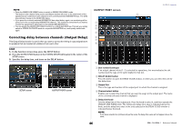
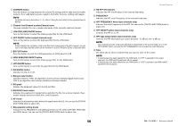
NOTE • Press the SENDS ON FADER button to switch to SENDS ON FADER mode. The faders in the Channel Strip section and Master section will move to the send levels of the signals that are routed from each channel to the currently-selected MIX/MATRIX bus. The [ON] keys will also change to the SEND ON status. • If you press the currently-selected MIX/MATRIX bus select button again, cue monitoring will be turned on for the corresponding MIX/MATRIX channel. This method is convenient if you want to monitor the signal that is being sent to the selected MIX/MATRIX bus. • You can assign the SENDS ON FADER function to a USER DEFINED key. This lets you quickly switch to SENDS ON FADER mode for a specific MIX/MATRIX bus, and quickly switch back again. Correcting delay between channels (Output Delay) This Output Delay function is useful when you want to correct the timing of output signals sent to speakers that are located at a distance from each other. STEP 1. In the Function Access Area, press the SETUP button. 2. Press the OUTPUT PORT button in the SYSTEM SETUP field located in the center of the SETUP screen. 3. Specifies the delay time, and turns on the DELAY button. SETUP screen OUTPUT PORT screen OUTPUT PORT screen 2 1 3 4 5 6 7 8 OUTPUT channels 9 0 1 Slot number/Card type If an output channel of slot 1-2 is selected for operations, this area indicates the slot number and the type of I/O card installed in that slot. 2 DELAY SCALE button Press this button to open the DELAY SCALE window, in which you can select the unit for the delay time. 3 Output Port This is the type and number of the output port to which the channel is assigned. 4 Channel select button Enables you to select the channel that you want to assign to the output port. The name of the currently-selected channel is displayed. 5 Delay time knob Sets the delay time of the output port. Press the knob to select it, and then operate the [TOUCH AND TURN] knob. The millisecond delay time value is indicated above the knob, and the delay time value in the units selected in the DELAY SCALE window is indicated below the knob. NOTE If you have selected ms (millisecond) as the scale, the delay time value will not appear above the knob. 46 Reference Manual
-
 1
1 -
2
-
3
-
4
-
5
-
6
-
7
-
8
-
9
-
10
-
11
-
12
-
13
-
14
-
15
-
16
-
17
-
18
-
19
-
20
-
21
-
22
-
23
-
24
-
25
-
26
-
27
-
28
-
29
-
30
-
31
-
32
-
33
-
34
-
35
-
36
-
37
-
38
-
39
-
40
-
 41
41 -
 42
42 -
 43
43 -
 44
44 -
 45
45 -
 46
46 -
 47
47 -
 48
48 -
 49
49 -
 50
50 -
 51
51 -
52
-
53
-
54
-
55
-
56
-
57
-
58
-
59
-
60
-
61
-
62
-
63
-
64
-
65
-
66
-
67
-
68
-
69
-
70
-
71
-
72
-
73
-
74
-
75
-
76
-
77
-
78
-
79
-
80
-
81
-
82
-
83
-
84
-
85
-
86
-
87
-
88
-
89
-
90
-
91
-
92
-
93
-
94
-
95
-
96
-
97
-
98
-
99
-
100
-
101
-
102
-
103
-
104
-
105
-
106
-
107
-
108
-
109
-
110
-
111
-
112
-
113
-
114
-
115
-
116
-
117
-
118
-
119
-
120
-
121
-
122
-
123
-
124
-
125
-
126
-
127
-
128
-
129
-
130
-
131
-
132
-
133
-
134
-
135
-
136
-
137
-
138
-
139
-
140
-
141
-
142
-
143
-
144
-
145
-
146
-
147
-
148
-
149
-
150
-
151
-
152
-
153
-
154
-
155
-
156
-
157
-
158
-
159
-
160
-
161
-
162
-
163
-
164
-
165
-
166
-
167
-
168
-
169
-
170
-
171
-
172
-
173
-
174
-
175
-
176
-
177
-
178
-
179
-
180
-
181
-
182
-
183
-
184
-
185
-
186
-
187
-
188
-
189
-
190
-
191
-
192
-
193
-
194
-
195
-
196
-
197
-
198
-
199
-
200
-
201
-
202
-
203
-
204
-
205
-
206
-
207
-
208
-
209
-
210
-
211
-
212
-
213
-
214
-
215
-
216
-
217
-
218
-
219
-
220
-
221
-
222
-
223
-
224
-
225
-
226
-
227
-
228
-
229
-
230
-
231
-
232
-
233
-
234
-
235
-
236
-
237
-
238
-
239
-
240
-
241
-
242
-
243
-
244
-
245
-
246
-
247
-
248
-
249
-
250
-
251
-
252
-
253
-
254
-
255
-
256
-
257
-
258
-
259
-
260
-
261
-
262
-
263
-
264
 |
 |
