Yamaha QL5 Reference Manual - Page 131
Remotely controlling an amp, I/O DEVICE HA window
 |
View all Yamaha QL5 manuals
Add to My Manuals
Save this manual to your list of manuals |
Page 131 highlights
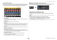
I/O DEVICE HA window Displayed when you press the rack in which the I/O device on the head amp side is mounted. You can remotely control the head amp of the I/O device from the QL series console by using the on-screen knobs and buttons or the [TOUCH AND TURN] knob on the top panel. 7 1 2 3 4 5 6 1 +48V MASTER Indicates the on/off status of the I/O device's master phantom power. (Switching this on or off is performed on the I/O device itself.) 2 +48V button These switch phantom power on/off for each channel. 3 GAIN knob Indicates the gain of the head amp on the I/O device. To adjust the value, press the knob to select it, and then use the [TOUCH AND TURN] knob. The level meter located at the immediate right of the knob indicates the input level for the corresponding port. 4 GC button Switches on or off the Gain Compensation function that maintains a consistent signal level on the audio network. 5 FREQUENCY knob/HPF button These controllers switch on or off the high-pass filter built into the head amp of the I/O device, and adjust its cutoff frequency. If you press and select the FREQUENCY knob, you can make adjustments using the [TOUCH AND TURN] knob. 6 Displayed port switch tabs These tabs switch the port that is displayed in the I/O DEVICE HA window. 7 GC ALL ON button/GC ALL OFF button Switch Gain Compensation on or off for all input channels simultaneously. I/O devices and external head amps Remotely controlling from the input channels To remotely control the I/O device's head amp from an input channel of the QL series console, operate the GAIN/PATCH window for the channel for which you want to control. Remotely controlling an amp This section explains how to remotely control an AMP unit that's connected to the Dante connector. STEP 1. Press the AMP tab in the upper part of the I/O DEVICE screen. 2. Press the I/O device displayed on the I/O DEVICE screen (AMP page). 3. Set the output port on the OUTPUT PATCH window, as necessary. Refer to step 7 in "I/O device patching" on page 127. 131 Reference Manual
-
 1
1 -
2
-
3
-
4
-
5
-
6
-
7
-
8
-
9
-
10
-
11
-
12
-
13
-
14
-
15
-
16
-
17
-
18
-
19
-
20
-
21
-
22
-
23
-
24
-
25
-
26
-
27
-
28
-
29
-
30
-
31
-
32
-
33
-
34
-
35
-
36
-
37
-
38
-
39
-
40
-
41
-
42
-
43
-
44
-
45
-
46
-
47
-
48
-
49
-
50
-
51
-
52
-
53
-
54
-
55
-
56
-
57
-
58
-
59
-
60
-
61
-
62
-
63
-
64
-
65
-
66
-
67
-
68
-
69
-
70
-
71
-
72
-
73
-
74
-
75
-
76
-
77
-
78
-
79
-
80
-
81
-
82
-
83
-
84
-
85
-
86
-
87
-
88
-
89
-
90
-
91
-
92
-
93
-
94
-
95
-
96
-
97
-
98
-
99
-
100
-
101
-
102
-
103
-
104
-
105
-
106
-
107
-
108
-
109
-
110
-
111
-
112
-
113
-
114
-
115
-
116
-
117
-
118
-
119
-
120
-
121
-
122
-
123
-
124
-
125
-
 126
126 -
 127
127 -
 128
128 -
 129
129 -
 130
130 -
 131
131 -
 132
132 -
 133
133 -
 134
134 -
 135
135 -
 136
136 -
137
-
138
-
139
-
140
-
141
-
142
-
143
-
144
-
145
-
146
-
147
-
148
-
149
-
150
-
151
-
152
-
153
-
154
-
155
-
156
-
157
-
158
-
159
-
160
-
161
-
162
-
163
-
164
-
165
-
166
-
167
-
168
-
169
-
170
-
171
-
172
-
173
-
174
-
175
-
176
-
177
-
178
-
179
-
180
-
181
-
182
-
183
-
184
-
185
-
186
-
187
-
188
-
189
-
190
-
191
-
192
-
193
-
194
-
195
-
196
-
197
-
198
-
199
-
200
-
201
-
202
-
203
-
204
-
205
-
206
-
207
-
208
-
209
-
210
-
211
-
212
-
213
-
214
-
215
-
216
-
217
-
218
-
219
-
220
-
221
-
222
-
223
-
224
-
225
-
226
-
227
-
228
-
229
-
230
-
231
-
232
-
233
-
234
-
235
-
236
-
237
-
238
-
239
-
240
-
241
-
242
-
243
-
244
-
245
-
246
-
247
-
248
-
249
-
250
-
251
-
252
-
253
-
254
-
255
-
256
-
257
-
258
-
259
-
260
-
261
-
262
-
263
-
264
 |
 |
