Yamaha QL5 Reference Manual - Page 16
Changing the output patch settings, Selecting the output port for each output channel
 |
View all Yamaha QL5 manuals
Add to My Manuals
Save this manual to your list of manuals |
Page 16 highlights
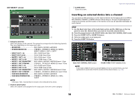
4 Category select list Selects the category of input port. The categories correspond to the following input ports. The displayed categories vary depending on the channel type. • DANTE1-32 ...........DANTE1-DANTE32 • DANTE33-64 .........DANTE33-DANTE64 (QL5 only) • INPUT/PB OUT......INPUT1-32*1, PB OUT(L), PB OUT(R) • SLOT1 SLOT1(1)-SLOT1(16) • SLOT2 SLOT2(1)-SLOT2(16) • EFFECT RACK ......FX1L(A)-FX8R(B) • PREMIUM RACK ...PR1L(A)-PR2R(B) *1. QL1: INPUT1-16 5 Port select buttons Select the input port that is assigned to the currently-selected channel. 6 Tabs Enable you to switch between items. 7 Close button Closes the screen. Input and output patching Changing the output patch settings To change the patching, you can either select the output port that will be the output destination of each output channel, or you can select the output channel that will be the output source for each output port. Selecting the output port for each output channel STEP 1. Press the Bank Select keys in the Fader Bank section and the [SEL] keys on the top panel to select an output channel. 2. Press the channel number/channel name field on the OVERVIEW screen. 3. Select the type of port in the category select list on the PATCH/NAME screen, and use the port select buttons to select the output port. OVERVIEW screen PATCH/NAME screen 16 Reference Manual
-
 1
1 -
2
-
3
-
4
-
5
-
6
-
7
-
8
-
9
-
10
-
 11
11 -
 12
12 -
 13
13 -
 14
14 -
 15
15 -
 16
16 -
 17
17 -
 18
18 -
 19
19 -
 20
20 -
 21
21 -
22
-
23
-
24
-
25
-
26
-
27
-
28
-
29
-
30
-
31
-
32
-
33
-
34
-
35
-
36
-
37
-
38
-
39
-
40
-
41
-
42
-
43
-
44
-
45
-
46
-
47
-
48
-
49
-
50
-
51
-
52
-
53
-
54
-
55
-
56
-
57
-
58
-
59
-
60
-
61
-
62
-
63
-
64
-
65
-
66
-
67
-
68
-
69
-
70
-
71
-
72
-
73
-
74
-
75
-
76
-
77
-
78
-
79
-
80
-
81
-
82
-
83
-
84
-
85
-
86
-
87
-
88
-
89
-
90
-
91
-
92
-
93
-
94
-
95
-
96
-
97
-
98
-
99
-
100
-
101
-
102
-
103
-
104
-
105
-
106
-
107
-
108
-
109
-
110
-
111
-
112
-
113
-
114
-
115
-
116
-
117
-
118
-
119
-
120
-
121
-
122
-
123
-
124
-
125
-
126
-
127
-
128
-
129
-
130
-
131
-
132
-
133
-
134
-
135
-
136
-
137
-
138
-
139
-
140
-
141
-
142
-
143
-
144
-
145
-
146
-
147
-
148
-
149
-
150
-
151
-
152
-
153
-
154
-
155
-
156
-
157
-
158
-
159
-
160
-
161
-
162
-
163
-
164
-
165
-
166
-
167
-
168
-
169
-
170
-
171
-
172
-
173
-
174
-
175
-
176
-
177
-
178
-
179
-
180
-
181
-
182
-
183
-
184
-
185
-
186
-
187
-
188
-
189
-
190
-
191
-
192
-
193
-
194
-
195
-
196
-
197
-
198
-
199
-
200
-
201
-
202
-
203
-
204
-
205
-
206
-
207
-
208
-
209
-
210
-
211
-
212
-
213
-
214
-
215
-
216
-
217
-
218
-
219
-
220
-
221
-
222
-
223
-
224
-
225
-
226
-
227
-
228
-
229
-
230
-
231
-
232
-
233
-
234
-
235
-
236
-
237
-
238
-
239
-
240
-
241
-
242
-
243
-
244
-
245
-
246
-
247
-
248
-
249
-
250
-
251
-
252
-
253
-
254
-
255
-
256
-
257
-
258
-
259
-
260
-
261
-
262
-
263
-
264
 |
 |
