Yamaha QL5 Reference Manual - Page 28
TAKE FROM PORT button, TAKE FROM CHANNEL button, 48V button, A.GAIN analog gain knob, Level meter,
 |
View all Yamaha QL5 manuals
Add to My Manuals
Save this manual to your list of manuals |
Page 28 highlights
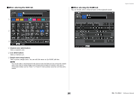
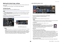
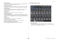
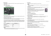
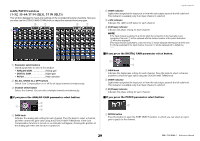
2 PATCH button Press this button to display the PORT SELECT window to patch the input port to the input channel. PORT SELECT window TAKE FROM CHANNEL button TAKE FROM PORT button • TAKE FROM PORT button The HA settings of the port will take priority. Even if you change the patching, the HA settings of the port will remain unchanged. • TAKE FROM CHANNEL button The HA settings of the channel will take priority. The HA settings of the port that had been previously patched will be copied to the newly-patched port. If the channel's HA settings are selected, the following HA settings will be copied from the channel to the port that is patched. If you patch the input channel from an input that does not have these settings (i.e., that does not have a HA), the default values will be specified. HA setting HA gain amount HPF on/off Phantom power on/off Gain compensation on/off Default value -6dB Off Off Off NOTE If you're newly patching a previously-unpatched input channel, the default values will be specified if the HA INFO field's TAKE FROM CHANNEL button is pressed. Input channels 3 HA section Appears if the head amp is patched to the input channel. NOTE If the slot (for which the connection to the head amp is not recognized) is patched, the type of the MY card will be displayed. • +48V button This button will appear for the input channel to which the head amp has been patched. Press the button to switch phantom power (+48V) on or off. • A.GAIN (analog gain) knob Indicates the analog gain of the head amp. You can use the [TOUCH AND TURN] knob to adjust the gain. If the Gain Compensation function is turned on, an indicator will appear, showing the position of the analog gain when the function is turned on. • Level meter Indicates the input signal level. • GC (Gain Compensation) button Switches the Gain Compensation function on or off for that channel. 4 AG-DG LINK button Turns the analog gain and digital gain link on or off. When the link is turned on, the digital gain is linked to adjustments made to the analog gain, even if Gain Compensation is on. 5 Ø (Phase) button Switches between normal and reverse phase settings of signals input. 6 D. GAIN (digital gain) knob Indicates the digital gain value. You can use the [TOUCH AND TURN] knob to adjust the gain. If the Gain Compensation function is turned on, digital gain will be used to adjust the level of the signal input to the input channels. 7 Digital gain meter Indicates the level after the signal passes through the digital gain. 8 GC ALL ON button/GC ALL OFF button Switch Gain Compensation on or off for all input channels simultaneously. 9 AG-DG ALL ON button/AG-DG ALL OFF button Switch all analog gain and digital gain links on or off simultaneously. 28 Reference Manual
-
 1
1 -
2
-
3
-
4
-
5
-
6
-
7
-
8
-
9
-
10
-
11
-
12
-
13
-
14
-
15
-
16
-
17
-
18
-
19
-
20
-
21
-
22
-
 23
23 -
 24
24 -
 25
25 -
 26
26 -
 27
27 -
 28
28 -
 29
29 -
 30
30 -
 31
31 -
 32
32 -
 33
33 -
34
-
35
-
36
-
37
-
38
-
39
-
40
-
41
-
42
-
43
-
44
-
45
-
46
-
47
-
48
-
49
-
50
-
51
-
52
-
53
-
54
-
55
-
56
-
57
-
58
-
59
-
60
-
61
-
62
-
63
-
64
-
65
-
66
-
67
-
68
-
69
-
70
-
71
-
72
-
73
-
74
-
75
-
76
-
77
-
78
-
79
-
80
-
81
-
82
-
83
-
84
-
85
-
86
-
87
-
88
-
89
-
90
-
91
-
92
-
93
-
94
-
95
-
96
-
97
-
98
-
99
-
100
-
101
-
102
-
103
-
104
-
105
-
106
-
107
-
108
-
109
-
110
-
111
-
112
-
113
-
114
-
115
-
116
-
117
-
118
-
119
-
120
-
121
-
122
-
123
-
124
-
125
-
126
-
127
-
128
-
129
-
130
-
131
-
132
-
133
-
134
-
135
-
136
-
137
-
138
-
139
-
140
-
141
-
142
-
143
-
144
-
145
-
146
-
147
-
148
-
149
-
150
-
151
-
152
-
153
-
154
-
155
-
156
-
157
-
158
-
159
-
160
-
161
-
162
-
163
-
164
-
165
-
166
-
167
-
168
-
169
-
170
-
171
-
172
-
173
-
174
-
175
-
176
-
177
-
178
-
179
-
180
-
181
-
182
-
183
-
184
-
185
-
186
-
187
-
188
-
189
-
190
-
191
-
192
-
193
-
194
-
195
-
196
-
197
-
198
-
199
-
200
-
201
-
202
-
203
-
204
-
205
-
206
-
207
-
208
-
209
-
210
-
211
-
212
-
213
-
214
-
215
-
216
-
217
-
218
-
219
-
220
-
221
-
222
-
223
-
224
-
225
-
226
-
227
-
228
-
229
-
230
-
231
-
232
-
233
-
234
-
235
-
236
-
237
-
238
-
239
-
240
-
241
-
242
-
243
-
244
-
245
-
246
-
247
-
248
-
249
-
250
-
251
-
252
-
253
-
254
-
255
-
256
-
257
-
258
-
259
-
260
-
261
-
262
-
263
-
264
 |
 |
