Yamaha QL5 Reference Manual - Page 160
User settings, User types and user authentication keys
 |
View all Yamaha QL5 manuals
Add to My Manuals
Save this manual to your list of manuals |
Page 160 highlights
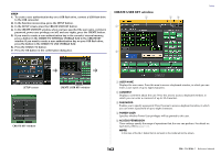
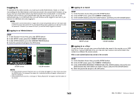
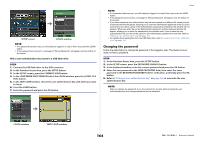
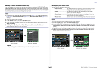
BUS SETUP field This field enables you to make bus-related settings. D BUS SETUP button Press this button to open the BUS SETUP window, in which you can make MIX bus/ MATRIX bus-related settings. DATE/TIME button Press this button to open the DATE/TIME window, in which you can set the date and time. NETWORK button Press this button to open the NETWORK window, in which you can set the network address. Indicator field This field displays various information about the console. E BATTERY indicator Indicates the status of the internal battery. NOTE The LOW or NO indication will appear if the battery runs down. In this case, immediately contact your Yamaha dealer or a Yamaha service center listed at the end of the operating manual (separate document) to have the backup battery replaced. F POWER SUPPLY indicator Indicates the currently-running power supply. • INT Internal G Version indicator Indicates the version number of the CPU and DANTE module. CONSOLE LOCK button This button executes the Console Lock function. If the console password has been set, pressing this button will open the AUTHORIZATION window. Enter the correct password to execute Console Lock. If the console password has not been set, pressing this button will execute Console Lock immediately. Setup CONTRAST/BRIGHTNESS field This field enables you to set the LCD brightness and contrast. H BANK A/BANK B buttons Select a bank to which you want to save the brightness and contrast settings. You can save two different settings in bank A and B, and switch between them if desired. I CONTRAST NAME knob Adjusts the contrast of the channel name display. J BRIGHTNESS NAME knob Adjusts the brightness of the channel name display. BRIGHTNESS CH COLOR knob Adjusts the brightness balance of the channel color and the channel name display. BRIGHTNESS SCREEN knob Adjusts the brightness of the display. BRIGHTNESS PANEL knob Adjusts the brightness of the panel LEDs. BRIGHTNESS LAMP knob Adjusts the brightness of the lamp connected to the LAMP connector. User settings User Level settings allow you to restrict the parameters that can be operated by each user, or to change the settings of USER DEFINED keys and preference settings for each user. Settings for each user can be stored as a "user authentication key" inside the console or together on a USB flash drive, allowing users to be switched easily. This can be convenient in the following situations. • Unintended or mistaken operation can be prevented. • The range of functionality operable by an outside engineer (guest engineer) can be limited. • In situations in which multiple operators alternate with each other, output settings etc. can be locked to prevent unintended operations. • Preferences of each operator can easily be switched. User types and user authentication keys There are three types of user, as follows. To operate the QL series console, you must log-in as a user. • Administrator.......... The administrator of the QL console can use all of its functionality. Only one set of Administrator settings is internally maintained in the console. The Administrator can create user authentication keys for other users. Even if the console was locked by another user, the administrator can use the administrator password to unlock it. 160 Reference Manual
-
 1
1 -
2
-
3
-
4
-
5
-
6
-
7
-
8
-
9
-
10
-
11
-
12
-
13
-
14
-
15
-
16
-
17
-
18
-
19
-
20
-
21
-
22
-
23
-
24
-
25
-
26
-
27
-
28
-
29
-
30
-
31
-
32
-
33
-
34
-
35
-
36
-
37
-
38
-
39
-
40
-
41
-
42
-
43
-
44
-
45
-
46
-
47
-
48
-
49
-
50
-
51
-
52
-
53
-
54
-
55
-
56
-
57
-
58
-
59
-
60
-
61
-
62
-
63
-
64
-
65
-
66
-
67
-
68
-
69
-
70
-
71
-
72
-
73
-
74
-
75
-
76
-
77
-
78
-
79
-
80
-
81
-
82
-
83
-
84
-
85
-
86
-
87
-
88
-
89
-
90
-
91
-
92
-
93
-
94
-
95
-
96
-
97
-
98
-
99
-
100
-
101
-
102
-
103
-
104
-
105
-
106
-
107
-
108
-
109
-
110
-
111
-
112
-
113
-
114
-
115
-
116
-
117
-
118
-
119
-
120
-
121
-
122
-
123
-
124
-
125
-
126
-
127
-
128
-
129
-
130
-
131
-
132
-
133
-
134
-
135
-
136
-
137
-
138
-
139
-
140
-
141
-
142
-
143
-
144
-
145
-
146
-
147
-
148
-
149
-
150
-
151
-
152
-
153
-
154
-
 155
155 -
 156
156 -
 157
157 -
 158
158 -
 159
159 -
 160
160 -
 161
161 -
 162
162 -
 163
163 -
 164
164 -
 165
165 -
166
-
167
-
168
-
169
-
170
-
171
-
172
-
173
-
174
-
175
-
176
-
177
-
178
-
179
-
180
-
181
-
182
-
183
-
184
-
185
-
186
-
187
-
188
-
189
-
190
-
191
-
192
-
193
-
194
-
195
-
196
-
197
-
198
-
199
-
200
-
201
-
202
-
203
-
204
-
205
-
206
-
207
-
208
-
209
-
210
-
211
-
212
-
213
-
214
-
215
-
216
-
217
-
218
-
219
-
220
-
221
-
222
-
223
-
224
-
225
-
226
-
227
-
228
-
229
-
230
-
231
-
232
-
233
-
234
-
235
-
236
-
237
-
238
-
239
-
240
-
241
-
242
-
243
-
244
-
245
-
246
-
247
-
248
-
249
-
250
-
251
-
252
-
253
-
254
-
255
-
256
-
257
-
258
-
259
-
260
-
261
-
262
-
263
-
264
 |
 |
