Yamaha QL5 Reference Manual - Page 97
MONITOR screen, TALKBACK window, INPUT TO TALKBACK patch button, 48V button, ANALOG GAIN knob
 |
View all Yamaha QL5 manuals
Add to My Manuals
Save this manual to your list of manuals |
Page 97 highlights
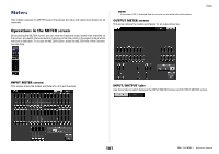
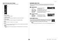
MONITOR screen In the MONITOR screen, the TALKBACK field enables you to check the current talkback settings, and turn talkback on or off. Talkback and Oscillator TALKBACK window Press the TALKBACK popup display button or the ASSIGN field to open the TALKBACK popup window. In this popup window you can make detailed settings for talkback. 1 2 3 1 2 3 4 1 TALKBACK display buttons When you press this button, the TALKBACK screen will appear, in which you can make detailed talkback settings. 2 INPUT TO TALKBACK field • INPUT TO TALKBACK patch button Press the button to open the PORT SELECT window, in which you can patch a desired input port to talkback. The selected port name will appear on the button. • INPUT GAIN knob Sets the input gain of the selected port. • Input level meter Indicates the level of signals after the input gain. 3 TALKBACK ASSIGN field An indicator lights to indicate the currently-selected output destination of the talkback signal. 4 TALKBACK ON button Switches talkback on or off. 1 INPUT TO TALKBACK field This field allows a mic connected to a conventional input port to be used as a talkback input. • INPUT TO TALKBACK patch button Press the button to open the PORT SELECT popup window, in which you can patch a desired input port to talkback. The selected port name will appear on the button. • +48V button This is an on/off switch for the phantom power (+48V) supplied to the selected input port. • ANALOG GAIN knob Adjusts the analog gain setting for the selected input port. If you press this knob, you can use the [TOUCH AND TURN] knob to adjust the gain. • HA meter Indicates the input level of a mic connected to the selected input port. • GC ON button Turns the Gain Compensation (gain correction function) on or off. The button will appear if the input jack of an I/O device is patched. • Gain Compensation meter Indicates the level after Gain Compensation. It will appear if the input jack of an I/O device is patched. NOTE These parameters and meters will not appear if no input port is selected. 97 Reference Manual
-
 1
1 -
2
-
3
-
4
-
5
-
6
-
7
-
8
-
9
-
10
-
11
-
12
-
13
-
14
-
15
-
16
-
17
-
18
-
19
-
20
-
21
-
22
-
23
-
24
-
25
-
26
-
27
-
28
-
29
-
30
-
31
-
32
-
33
-
34
-
35
-
36
-
37
-
38
-
39
-
40
-
41
-
42
-
43
-
44
-
45
-
46
-
47
-
48
-
49
-
50
-
51
-
52
-
53
-
54
-
55
-
56
-
57
-
58
-
59
-
60
-
61
-
62
-
63
-
64
-
65
-
66
-
67
-
68
-
69
-
70
-
71
-
72
-
73
-
74
-
75
-
76
-
77
-
78
-
79
-
80
-
81
-
82
-
83
-
84
-
85
-
86
-
87
-
88
-
89
-
90
-
91
-
 92
92 -
 93
93 -
 94
94 -
 95
95 -
 96
96 -
 97
97 -
 98
98 -
 99
99 -
 100
100 -
 101
101 -
 102
102 -
103
-
104
-
105
-
106
-
107
-
108
-
109
-
110
-
111
-
112
-
113
-
114
-
115
-
116
-
117
-
118
-
119
-
120
-
121
-
122
-
123
-
124
-
125
-
126
-
127
-
128
-
129
-
130
-
131
-
132
-
133
-
134
-
135
-
136
-
137
-
138
-
139
-
140
-
141
-
142
-
143
-
144
-
145
-
146
-
147
-
148
-
149
-
150
-
151
-
152
-
153
-
154
-
155
-
156
-
157
-
158
-
159
-
160
-
161
-
162
-
163
-
164
-
165
-
166
-
167
-
168
-
169
-
170
-
171
-
172
-
173
-
174
-
175
-
176
-
177
-
178
-
179
-
180
-
181
-
182
-
183
-
184
-
185
-
186
-
187
-
188
-
189
-
190
-
191
-
192
-
193
-
194
-
195
-
196
-
197
-
198
-
199
-
200
-
201
-
202
-
203
-
204
-
205
-
206
-
207
-
208
-
209
-
210
-
211
-
212
-
213
-
214
-
215
-
216
-
217
-
218
-
219
-
220
-
221
-
222
-
223
-
224
-
225
-
226
-
227
-
228
-
229
-
230
-
231
-
232
-
233
-
234
-
235
-
236
-
237
-
238
-
239
-
240
-
241
-
242
-
243
-
244
-
245
-
246
-
247
-
248
-
249
-
250
-
251
-
252
-
253
-
254
-
255
-
256
-
257
-
258
-
259
-
260
-
261
-
262
-
263
-
264
 |
 |
