Yamaha QL5 Reference Manual - Page 147
RECORDER screen when selecting the USB tab, CH SELECT window, CH1-64 QL5
 |
View all Yamaha QL5 manuals
Add to My Manuals
Save this manual to your list of manuals |
Page 147 highlights
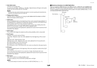
RECORDER screen (when selecting the USB tab) In this screen you can assign signals to the input and output of the USB memory recorder, and perform recording and playback operations. Recorder 7 PLAYBACK OUTPUT CUE button Press this button to monitor the signal output from the recorder. NOTE You cannot turn on this button and the RECORDER INPUT CUE button simultaneously. 8 Meters Indicate the level of the signals output to the recorder. CH SELECT window Display this window by pressing the RECORDER INPUT L or R button or the PLAYBACK OUTPUT L or R button. 1 1 2 2 1 23 4 8 76 5 1 RECORDER INPUT L/R buttons Press these buttons to open the CH SELECT window, in which you can select the signals patched to the recorder's L/R input channels. 2 RECORDER INPUT GAIN knob Sets the level of the signal input to the recorder. 3 RECORDER INPUT CUE button When this button is turned on, you can monitor the signal input to the recorder. NOTE You cannot turn on this button and the PLAYBACK OUTPUT CUE button simultaneously. 4 Meters Indicate the level of the signals input to the recorder. 5 PLAYBACK OUTPUT L/R buttons Press these buttons to open the CH SELECT window, in which you can select the signals patched to the recorder's L/R output channels for playback. 6 PLAYBACK OUTPUT GAIN knob Sets the level of the signal output to the recorder. 1 Category List Enables you to select the type of channel. 2 Channel select button Select the channels that will be patched to the USB memory recorder's inputs and outputs. The channels that can be patched at input or output are different. Channels that can be patched to the recorder's inputs • MIX 1-16 MIX channels 1-16 • MTRX 1-8 MATRIX channels 1-8 • ST L/R STEREO channel L/R • ST L+C STEREO channel L mixed with the MONO(C) channel • ST R+C STEREO channel R mixed with the MONO(C) channel • MONO MONO channel • CH1-64 (QL5), CH1-32 (QL1 Direct output of an INPUT channel 1-64 (QL5) or INPUT channel 1-32 (QL1) • INPUT INPUT1-32 (QL1: INPUT1-16) • SLOT1 IN SLOT1(1)-SLOT1(16) • SLOT2 IN SLOT2(1)-SLOT2(16) • DANTE1-32 DANTE1-DANTE32 • DANTE33-64 DANTE33-DANTE64 (QL5 only) 147 Reference Manual
-
 1
1 -
2
-
3
-
4
-
5
-
6
-
7
-
8
-
9
-
10
-
11
-
12
-
13
-
14
-
15
-
16
-
17
-
18
-
19
-
20
-
21
-
22
-
23
-
24
-
25
-
26
-
27
-
28
-
29
-
30
-
31
-
32
-
33
-
34
-
35
-
36
-
37
-
38
-
39
-
40
-
41
-
42
-
43
-
44
-
45
-
46
-
47
-
48
-
49
-
50
-
51
-
52
-
53
-
54
-
55
-
56
-
57
-
58
-
59
-
60
-
61
-
62
-
63
-
64
-
65
-
66
-
67
-
68
-
69
-
70
-
71
-
72
-
73
-
74
-
75
-
76
-
77
-
78
-
79
-
80
-
81
-
82
-
83
-
84
-
85
-
86
-
87
-
88
-
89
-
90
-
91
-
92
-
93
-
94
-
95
-
96
-
97
-
98
-
99
-
100
-
101
-
102
-
103
-
104
-
105
-
106
-
107
-
108
-
109
-
110
-
111
-
112
-
113
-
114
-
115
-
116
-
117
-
118
-
119
-
120
-
121
-
122
-
123
-
124
-
125
-
126
-
127
-
128
-
129
-
130
-
131
-
132
-
133
-
134
-
135
-
136
-
137
-
138
-
139
-
140
-
141
-
 142
142 -
 143
143 -
 144
144 -
 145
145 -
 146
146 -
 147
147 -
 148
148 -
 149
149 -
 150
150 -
 151
151 -
 152
152 -
153
-
154
-
155
-
156
-
157
-
158
-
159
-
160
-
161
-
162
-
163
-
164
-
165
-
166
-
167
-
168
-
169
-
170
-
171
-
172
-
173
-
174
-
175
-
176
-
177
-
178
-
179
-
180
-
181
-
182
-
183
-
184
-
185
-
186
-
187
-
188
-
189
-
190
-
191
-
192
-
193
-
194
-
195
-
196
-
197
-
198
-
199
-
200
-
201
-
202
-
203
-
204
-
205
-
206
-
207
-
208
-
209
-
210
-
211
-
212
-
213
-
214
-
215
-
216
-
217
-
218
-
219
-
220
-
221
-
222
-
223
-
224
-
225
-
226
-
227
-
228
-
229
-
230
-
231
-
232
-
233
-
234
-
235
-
236
-
237
-
238
-
239
-
240
-
241
-
242
-
243
-
244
-
245
-
246
-
247
-
248
-
249
-
250
-
251
-
252
-
253
-
254
-
255
-
256
-
257
-
258
-
259
-
260
-
261
-
262
-
263
-
264
 |
 |
