Yamaha QL5 Reference Manual - Page 23
Input channels, Signal flow for input channels
 |
View all Yamaha QL5 manuals
Add to My Manuals
Save this manual to your list of manuals |
Page 23 highlights
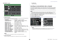
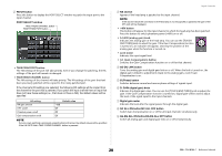
Input channels This chapter explains various operations for input channels. Signal flow for input channels The input channels comprise the section that processes signals received from the I/O devices, rear panel input jacks, or slots 1-2, and sends them to the STEREO bus, MONO bus, MIX buses, or MATRIX buses. There are two types of input channels, as follows. INPUT channel (monaural) These channels are used to process monaural signals. When the QL series console is in the default state, the signal from the analog input connector is assigned. ST IN channel (stereo) These channels are used to process stereo signals. When the QL series console is in the default state, the input signals from EFFECT RACKS 5-8 are assigned to ST IN 1-4. There are no assignments for ST IN 5-8. INPUT PATCH CH 1-64{32},ST IN 1L-8R To RACKIN PATCH INSERT POINT To OUTPUT PATCH CH INSERT OUT 1-64{32} POST ON INSERT OUT PRE FADER INSERT OUT PRE EQ INSERT OUT PRE HPF / PRE EQ / PRE FADER/POST ON ON LEVEL DIRECT OUT 1-64{32} To OUTPUT PATCH CH INSERT IN 1-64{32} PRE DG POST DG METER PRE EQ METER EQ OUT METER DYNA1OUT DYNA2OUT PRE FADER METER METER METER POST ON METER PAN POST PAN L POST PAN R LR MONO TO MONO TO ST PAN MODE METER 80 {48} OSCILLATOR Digital GAIN GR METER GR METER HPF INSERT ATT 4BAND EQ PRE HPF PRE EQ POST EQ PRE EQ INSERT OUT Keyin GATE DUCK EXPAND COMP COMP COMPAND DE-ESSER KEYIN CUE Keyin Filter INSERT DELAY Max 1000ms LEVEL/ DCA1-16 ON PRE FADER PRE FADER INSERT OUT INSERT LCR CSR POST ON POST ON INSERT OUT PAN LINK TO LCR Self PRE EQ Self POST EQ MIX13-16 OUT CH[1-8,9-16,17-24,25-32,33-40,41-48, 49-56, 57-64,ST IN 1L-8R]POST EQ(QL5) To MIX FIXED POST ON ON ON ON ON MIX1,3...15 MIX2,4...16 CH[1-8,9-16,17-24,25-32,ST IN 1L-8R]POST EQ(QL1) To MIX POST PAN L ON ON FIXED STEREO POST PAN R ON ON ST L MONO(C) ST R To MIX VARI PRE EQ / PRE FADER / POST ON ON ON LEVEL ON ON LEVEL To MIX VARI STEREO PRE EQ / PRE FADER / POST ON ON ON LEVEL PAN To MATRIX PRE EQ / PRE FADER / POST ON VARI ON ON LEVEL ON ON LEVEL MATRIX1,3...7 MATRIX2,4...8 (PRE FADER)PFL / (POST ON)AFL / POST PAN L (PRE FADER)PFL / (POST ON)AFL / POST PAN R To MATRIX PRE EQ / PRE FADER / POST ON VARI STEREO ON ON ON ON LEVEL PAN CUE L CUE R MIX 1 2 1516 M O N ST O MATRIX CUE L R(C) 1 2 7 8 L R • INPUT PATCH Assigns input signals to the input channels. • Ø (phase) Switches the phase of the input signal. • DIGITAL GAIN Attenuates/boosts the level of the input signal. Input channels • HPF (High Pass Filter) Cuts the region below the specified frequency. • 4 BAND EQ (4 band equalizer) A parametric EQ with four bands: HIGH, HIGH MID, LOW MID, and LOW. • DYNAMICS 1 This is a dynamics processor that can be used for gating, ducking, expander, or compressor. • DYNAMICS 2 This is a dynamics processor that can be used as a compressor, compander, or de-esser. • INPUT DELAY Corrects input signal delay. You can specify up to 1000ms. • LEVEL/DCA 1-16 Adjusts the input level of the effect. • ON (On/off) Turns the input channel on or off. If this is off, the corresponding channel will be muted. • PAN Adjusts the panning of signals sent from the input channel to the STEREO bus. For the ST IN channel (stereo), you can switch between PAN and BALANCE. The BALANCE parameter adjusts the volume balance of the left/right signals sent from the ST IN channel (stereo) to the STEREO bus. You can turn on PAN LINK in the BUS SETUP window so that the setting of the PAN parameter will also be applied to signals sent to two MIX or MATRIX buses that are set to stereo. • LCR (Left/Center/Right) Sends the input channel signal to the STEREO bus/MONO bus as a three-channel signal that consists of the L/R channels plus the center channel. • MIX ON/OFF (MIX send on/off) This is an on/off switch for signals sent from the input channel to MIX buses 1-16. • MIX LEVEL 1-16 (MIX send levels 1-16) Adjusts the send level of signals sent from the input channel to VARI type MIX buses 1- 16. As the position from which the signal is sent to the MIX bus, you can choose from the following: immediately before EQ, pre-fader, or post-fader. • MATRIX ON/OFF (MATRIX send on/off) This is an on/off switch for signals sent from the input channel to MATRIX buses 1-8. • MATRIX LEVEL 1-8 (MATRIX send levels 1-8) Adjusts the send level of the signal sent from the input channel to MATRIX buses 1-8. As the position from which the signal is sent to the MATRIX bus, you can choose from the following: immediately before the EQ, pre-fader, or post-fader. 23 Reference Manual
-
 1
1 -
2
-
3
-
4
-
5
-
6
-
7
-
8
-
9
-
10
-
11
-
12
-
13
-
14
-
15
-
16
-
17
-
 18
18 -
 19
19 -
 20
20 -
 21
21 -
 22
22 -
 23
23 -
 24
24 -
 25
25 -
 26
26 -
 27
27 -
 28
28 -
29
-
30
-
31
-
32
-
33
-
34
-
35
-
36
-
37
-
38
-
39
-
40
-
41
-
42
-
43
-
44
-
45
-
46
-
47
-
48
-
49
-
50
-
51
-
52
-
53
-
54
-
55
-
56
-
57
-
58
-
59
-
60
-
61
-
62
-
63
-
64
-
65
-
66
-
67
-
68
-
69
-
70
-
71
-
72
-
73
-
74
-
75
-
76
-
77
-
78
-
79
-
80
-
81
-
82
-
83
-
84
-
85
-
86
-
87
-
88
-
89
-
90
-
91
-
92
-
93
-
94
-
95
-
96
-
97
-
98
-
99
-
100
-
101
-
102
-
103
-
104
-
105
-
106
-
107
-
108
-
109
-
110
-
111
-
112
-
113
-
114
-
115
-
116
-
117
-
118
-
119
-
120
-
121
-
122
-
123
-
124
-
125
-
126
-
127
-
128
-
129
-
130
-
131
-
132
-
133
-
134
-
135
-
136
-
137
-
138
-
139
-
140
-
141
-
142
-
143
-
144
-
145
-
146
-
147
-
148
-
149
-
150
-
151
-
152
-
153
-
154
-
155
-
156
-
157
-
158
-
159
-
160
-
161
-
162
-
163
-
164
-
165
-
166
-
167
-
168
-
169
-
170
-
171
-
172
-
173
-
174
-
175
-
176
-
177
-
178
-
179
-
180
-
181
-
182
-
183
-
184
-
185
-
186
-
187
-
188
-
189
-
190
-
191
-
192
-
193
-
194
-
195
-
196
-
197
-
198
-
199
-
200
-
201
-
202
-
203
-
204
-
205
-
206
-
207
-
208
-
209
-
210
-
211
-
212
-
213
-
214
-
215
-
216
-
217
-
218
-
219
-
220
-
221
-
222
-
223
-
224
-
225
-
226
-
227
-
228
-
229
-
230
-
231
-
232
-
233
-
234
-
235
-
236
-
237
-
238
-
239
-
240
-
241
-
242
-
243
-
244
-
245
-
246
-
247
-
248
-
249
-
250
-
251
-
252
-
253
-
254
-
255
-
256
-
257
-
258
-
259
-
260
-
261
-
262
-
263
-
264
 |
 |
