Yamaha QL5 Reference Manual - Page 168
Identify I/o Device Port By [sel], Popup Appears When Knobs Pressed
 |
View all Yamaha QL5 manuals
Add to My Manuals
Save this manual to your list of manuals |
Page 168 highlights
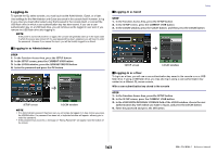
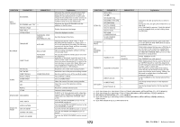
• DIGITAL I/O ERROR If this is on, an error message will appear when a digital audio I/O error occurs. • MIDI I/O ERROR If this is on, an error message will appear when a MIDI transmit/receive error occurs. 5 PANEL OPERATION field Enables you to make settings for options related to panel operation. • AUTO CHANNEL SELECT Specifies whether the corresponding channel will be selected when you operate the [ON] key or fader for the channel. You can set this parameter separately for INPUT (input channels) and OUTPUT (output channels). • [CUE] [SEL] LINK Specifies whether channel selection will be linked with cue operations. If the LINK button is on, channels for which cue operations were performed will be selected. • [FADER BANK] [SEL] LINK Specifies whether channel selection will be linked with fader bank selection. You can set this parameter separately for INPUT (input channels), OUTPUT (output channels), and CUSTOM (Custom fader bank). If the LINK button is on, and you select the corresponding fader bank, the channel in that bank that was selected most recently will be selected, and its [SEL] key will light. • IDENTIFY I/O DEVICE PORT BY [SEL] Specifies whether to enable a function that allows you to identify the I/O device port connected to a channel by pressing the [SEL] key for that channel. If this ON button is lit, pressing a [SEL] key on the panel will cause the signal indicator to flash for the port of the I/O device that is assigned to the corresponding channel by the INPUT PATCH/OUTPUT PATCH settings. • POPUP APPEARS WHEN KNOB(S) PRESSED Specifies whether pressing a knob in the SELECTED CHANNEL section of the panel while the SELECTED CHANNEL VIEW screen is displayed will cause a window (1ch) to appear. If the ON button is lit, a window (1ch) will open (or close) whenever you press a knob. NOTE If you press the SEND or PAN knob, a window (8ch) will open. • GAIN KNOB FUNCTION Specifies what will happen when you operate the [TOUCH AND TURN] knob. When ANALOG GAIN button is lit, you can adjust analog gain on the head amp. When DIGITAL GAIN button is lit, you can adjust digital gain on the console. • SCENE UP/DOWN Specifies what the USER DEFINED key assigned to INC RECALL or DEC RECALL will do when pressed in the SCENE windows. When the SCENE +1/-1 button is lit, pressing the USER DEFINED key assigned to INC RECALL or DEC RECALL will increment or decrement the scene number. When the LIST UP/DOWN button is lit, pressing the USER DEFINED key assigned to INC RECALL or DEC RECALL will scroll the list upward or downward. Setup • LIST ORDER Specifies the order in which scene memories and library items will appear on the list. When the NORMAL button is lit, the list appears in ascending numerical order. When the REVERSE button is lit, the list appears in descending numerical order. • NAME DISPLAY Specifies the content of the name display in the Channel Strip section. When the NAME ONLY button is lit, the channel name and the channel number appear. When the GR METER button is lit, GR METER information and fader level are also displayed. NOTE The GR METER simply lets you confirm the changes in gain reduction. GR METER display Highlighted display (The channel is off in SENDS ON FADER mode.) 168 Reference Manual
-
 1
1 -
2
-
3
-
4
-
5
-
6
-
7
-
8
-
9
-
10
-
11
-
12
-
13
-
14
-
15
-
16
-
17
-
18
-
19
-
20
-
21
-
22
-
23
-
24
-
25
-
26
-
27
-
28
-
29
-
30
-
31
-
32
-
33
-
34
-
35
-
36
-
37
-
38
-
39
-
40
-
41
-
42
-
43
-
44
-
45
-
46
-
47
-
48
-
49
-
50
-
51
-
52
-
53
-
54
-
55
-
56
-
57
-
58
-
59
-
60
-
61
-
62
-
63
-
64
-
65
-
66
-
67
-
68
-
69
-
70
-
71
-
72
-
73
-
74
-
75
-
76
-
77
-
78
-
79
-
80
-
81
-
82
-
83
-
84
-
85
-
86
-
87
-
88
-
89
-
90
-
91
-
92
-
93
-
94
-
95
-
96
-
97
-
98
-
99
-
100
-
101
-
102
-
103
-
104
-
105
-
106
-
107
-
108
-
109
-
110
-
111
-
112
-
113
-
114
-
115
-
116
-
117
-
118
-
119
-
120
-
121
-
122
-
123
-
124
-
125
-
126
-
127
-
128
-
129
-
130
-
131
-
132
-
133
-
134
-
135
-
136
-
137
-
138
-
139
-
140
-
141
-
142
-
143
-
144
-
145
-
146
-
147
-
148
-
149
-
150
-
151
-
152
-
153
-
154
-
155
-
156
-
157
-
158
-
159
-
160
-
161
-
162
-
 163
163 -
 164
164 -
 165
165 -
 166
166 -
 167
167 -
 168
168 -
 169
169 -
 170
170 -
 171
171 -
 172
172 -
 173
173 -
174
-
175
-
176
-
177
-
178
-
179
-
180
-
181
-
182
-
183
-
184
-
185
-
186
-
187
-
188
-
189
-
190
-
191
-
192
-
193
-
194
-
195
-
196
-
197
-
198
-
199
-
200
-
201
-
202
-
203
-
204
-
205
-
206
-
207
-
208
-
209
-
210
-
211
-
212
-
213
-
214
-
215
-
216
-
217
-
218
-
219
-
220
-
221
-
222
-
223
-
224
-
225
-
226
-
227
-
228
-
229
-
230
-
231
-
232
-
233
-
234
-
235
-
236
-
237
-
238
-
239
-
240
-
241
-
242
-
243
-
244
-
245
-
246
-
247
-
248
-
249
-
250
-
251
-
252
-
253
-
254
-
255
-
256
-
257
-
258
-
259
-
260
-
261
-
262
-
263
-
264
 |
 |
