Yamaha QL5 Reference Manual - Page 27
GAIN/PATCH window 8ch, GC ALL ON button/GC ALL OFF button
 |
View all Yamaha QL5 manuals
Add to My Manuals
Save this manual to your list of manuals |
Page 27 highlights
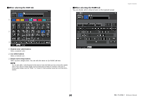
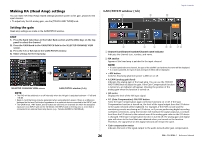
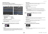
3 INPUT PORT button Indicates the port that is assigned to the channel. Press this button to display the PORT SELECT window, in which you can select a port to patch. 4 Icon/Channel name button Indicates the channel number, icon, and name. Press this button to access the PATCH/ NAME window, in which you can patch the input port and specify the channel name. 5 AG-DG LINK button Turns the analog gain and digital gain link on or off. When the link is turned on, the digital gain is linked to adjustments made to the analog gain, even if Gain Compensation is on. 6 Ø (Phase) button Switches between normal and reverse phase settings of signals input. 7 D. GAIN (digital gain) knob Indicates the digital gain value. You can use the [TOUCH AND TURN] knob to adjust the digital gain. If the Gain Compensation function is turned on, no changes will be made to the input level of the analog gain, and therefore the input gain is adjusted with the digital gain. 8 Digital gain meter Indicates the level after the signal passes through the digital gain. 9 GC ALL ON button/GC ALL OFF button Switch Gain Compensation on or off for all input channels simultaneously. 0 AG-DG ALL ON button/AG-DG ALL OFF button Switch all analog gain and digital gain links on or off simultaneously. GAIN/PATCH window (8ch) 8 9 Input channels 1 2 3 4 5 6 7 1 Channel select button Indicates the channel icon, number, and name. When you press this button, the corresponding channel will become a target for operations in the SELECTED CHANNEL section, and the corresponding [SEL] key will light. 27 Reference Manual
-
 1
1 -
2
-
3
-
4
-
5
-
6
-
7
-
8
-
9
-
10
-
11
-
12
-
13
-
14
-
15
-
16
-
17
-
18
-
19
-
20
-
21
-
 22
22 -
 23
23 -
 24
24 -
 25
25 -
 26
26 -
 27
27 -
 28
28 -
 29
29 -
 30
30 -
 31
31 -
 32
32 -
33
-
34
-
35
-
36
-
37
-
38
-
39
-
40
-
41
-
42
-
43
-
44
-
45
-
46
-
47
-
48
-
49
-
50
-
51
-
52
-
53
-
54
-
55
-
56
-
57
-
58
-
59
-
60
-
61
-
62
-
63
-
64
-
65
-
66
-
67
-
68
-
69
-
70
-
71
-
72
-
73
-
74
-
75
-
76
-
77
-
78
-
79
-
80
-
81
-
82
-
83
-
84
-
85
-
86
-
87
-
88
-
89
-
90
-
91
-
92
-
93
-
94
-
95
-
96
-
97
-
98
-
99
-
100
-
101
-
102
-
103
-
104
-
105
-
106
-
107
-
108
-
109
-
110
-
111
-
112
-
113
-
114
-
115
-
116
-
117
-
118
-
119
-
120
-
121
-
122
-
123
-
124
-
125
-
126
-
127
-
128
-
129
-
130
-
131
-
132
-
133
-
134
-
135
-
136
-
137
-
138
-
139
-
140
-
141
-
142
-
143
-
144
-
145
-
146
-
147
-
148
-
149
-
150
-
151
-
152
-
153
-
154
-
155
-
156
-
157
-
158
-
159
-
160
-
161
-
162
-
163
-
164
-
165
-
166
-
167
-
168
-
169
-
170
-
171
-
172
-
173
-
174
-
175
-
176
-
177
-
178
-
179
-
180
-
181
-
182
-
183
-
184
-
185
-
186
-
187
-
188
-
189
-
190
-
191
-
192
-
193
-
194
-
195
-
196
-
197
-
198
-
199
-
200
-
201
-
202
-
203
-
204
-
205
-
206
-
207
-
208
-
209
-
210
-
211
-
212
-
213
-
214
-
215
-
216
-
217
-
218
-
219
-
220
-
221
-
222
-
223
-
224
-
225
-
226
-
227
-
228
-
229
-
230
-
231
-
232
-
233
-
234
-
235
-
236
-
237
-
238
-
239
-
240
-
241
-
242
-
243
-
244
-
245
-
246
-
247
-
248
-
249
-
250
-
251
-
252
-
253
-
254
-
255
-
256
-
257
-
258
-
259
-
260
-
261
-
262
-
263
-
264
 |
 |
