Yamaha QL5 Reference Manual - Page 19
INSERT/DIRECT OUT window 1ch, INSERT screen 8ch, INSERT field, INSERT IN HA field
 |
View all Yamaha QL5 manuals
Add to My Manuals
Save this manual to your list of manuals |
Page 19 highlights
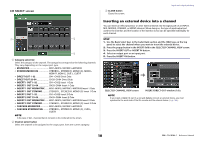
INSERT/DIRECT OUT window (1ch) 3 67 67 9 9 8 12 4 5 INSERT field This field enables you to make insert settings. Press one of three fields to choose PRE HPF (immediately before the HPF), PRE EQ (immediately before the EQ) or PRE FADER (immediately before the fader), or POST ON (immediately after the [ON] key) as the insert position. 1 INSERT OUT button Displays the currently-selected output port for insert 1 and insert 2. Press this button to open the PORT SELECT window, and select an output port. 2 INSERT IN button Displays the currently-selected input port for insert 1 and insert 2. Press this button to open the PORT SELECT window, in which you can select an input port. 3 INSERT ON/OFF button Switches the insert on or off. 4 APPLY TO ALL INPUT button (input channels only) Specifies whether the insert point/direct out point settings will be applied to all input channels. 5 APPLY TO ALL OUTPUT button (output channels only) Specifies whether the insert point setting will be applied to all output channels. Input and output patching INSERT IN HA field This field will appear if you have selected an input port (that features a head amp) as the insert-in. 6 +48V button Switches head amp phantom power (+48V) (currently-selected for insert 1 and insert 2) on or off. 7 A.GAIN knob Indicates the currently-selected head amp analog gain setting for insert 1 and insert 2. You can use the [TOUCH AND TURN] knob to adjust the gain. NOTE • If you have selected the INPUT jack on the QL console as the input port for insert-in, make the HA settings in the INSERT IN HA field. • Even if the INSERT ON/OFF button is OFF, the signal selected for insert-out will continue to be sent. 8 HA meter Displays the level of the currently-selected head amp input signal for insert 1 and insert 2. 9 Close button Closes the screen. INSERT screen (8ch) 1 2 3 4 3 4 1 Channel select button Selects the channel to set. The channel icon, color, and number appear. 19 Reference Manual
-
 1
1 -
2
-
3
-
4
-
5
-
6
-
7
-
8
-
9
-
10
-
11
-
12
-
13
-
 14
14 -
 15
15 -
 16
16 -
 17
17 -
 18
18 -
 19
19 -
 20
20 -
 21
21 -
 22
22 -
 23
23 -
 24
24 -
25
-
26
-
27
-
28
-
29
-
30
-
31
-
32
-
33
-
34
-
35
-
36
-
37
-
38
-
39
-
40
-
41
-
42
-
43
-
44
-
45
-
46
-
47
-
48
-
49
-
50
-
51
-
52
-
53
-
54
-
55
-
56
-
57
-
58
-
59
-
60
-
61
-
62
-
63
-
64
-
65
-
66
-
67
-
68
-
69
-
70
-
71
-
72
-
73
-
74
-
75
-
76
-
77
-
78
-
79
-
80
-
81
-
82
-
83
-
84
-
85
-
86
-
87
-
88
-
89
-
90
-
91
-
92
-
93
-
94
-
95
-
96
-
97
-
98
-
99
-
100
-
101
-
102
-
103
-
104
-
105
-
106
-
107
-
108
-
109
-
110
-
111
-
112
-
113
-
114
-
115
-
116
-
117
-
118
-
119
-
120
-
121
-
122
-
123
-
124
-
125
-
126
-
127
-
128
-
129
-
130
-
131
-
132
-
133
-
134
-
135
-
136
-
137
-
138
-
139
-
140
-
141
-
142
-
143
-
144
-
145
-
146
-
147
-
148
-
149
-
150
-
151
-
152
-
153
-
154
-
155
-
156
-
157
-
158
-
159
-
160
-
161
-
162
-
163
-
164
-
165
-
166
-
167
-
168
-
169
-
170
-
171
-
172
-
173
-
174
-
175
-
176
-
177
-
178
-
179
-
180
-
181
-
182
-
183
-
184
-
185
-
186
-
187
-
188
-
189
-
190
-
191
-
192
-
193
-
194
-
195
-
196
-
197
-
198
-
199
-
200
-
201
-
202
-
203
-
204
-
205
-
206
-
207
-
208
-
209
-
210
-
211
-
212
-
213
-
214
-
215
-
216
-
217
-
218
-
219
-
220
-
221
-
222
-
223
-
224
-
225
-
226
-
227
-
228
-
229
-
230
-
231
-
232
-
233
-
234
-
235
-
236
-
237
-
238
-
239
-
240
-
241
-
242
-
243
-
244
-
245
-
246
-
247
-
248
-
249
-
250
-
251
-
252
-
253
-
254
-
255
-
256
-
257
-
258
-
259
-
260
-
261
-
262
-
263
-
264
 |
 |
