Yamaha QL5 Reference Manual - Page 41
Specifying the channel name, icon, and channel color, RACK IN PATCH
 |
View all Yamaha QL5 manuals
Add to My Manuals
Save this manual to your list of manuals |
Page 41 highlights
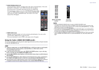
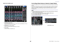
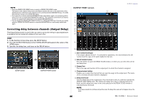
• MATRIX ON/OFF (MATRIX send on/off) This is an on/off switch for signals sent from the MIX channels, STEREO (L/R) channel, or MONO (C) channel to each MATRIX bus. • MATRIX (MATRIX send level) Adjusts the send level of signals sent from the MIX channels, STEREO (L/R) channel, or MONO (C) channel to each MATRIX bus 1-8. For the position from which the signal will be sent to the MATRIX bus, you can choose either immediately before the fader, or immediately after the [ON] key. If the send-destination MATRIX bus is set to stereo, you can use the PAN knob to adjust the panning between the two MATRIX buses. If the send-source is a stereo MIX channel or the STEREO channel, use the BALANCE knob to adjust the volume balance of the left and right channels sent to the two MATRIX buses. • INSERT You can patch the desired output/input ports to insert an external device such as an effect processor. You can switch the insert-out and insert-in locations. • METER Indicates the level of the output channel. You can switch the position at which the level is detected. • KEY IN (MIX channels 13-16 only) You can send the output signals of MIX channels 13-16 to dynamics processors and use them as key-in signals to control the dynamics. • RACK IN PATCH Patches the output signal of an output channel to an input of the rack. • OUTPUT PATCH Assigns an output port to an output channel. • MONITOR SELECT Selects the output signal of an output channel as a monitor source. OUTPUT channels Specifying the channel name, icon, and channel color STEP 1. Press the Bank Select keys in the Fader Bank section and the [SEL] keys on the top panel to select an output channel. 2. In the OVERVIEW screen, press the channel number/channel name field of the channel for which you want to specify the channel name, icon, and channel color. 3. Follow the steps for the input channels (page 24). OVERVIEW screen PATCH/NAME screen 41 Reference Manual
-
 1
1 -
2
-
3
-
4
-
5
-
6
-
7
-
8
-
9
-
10
-
11
-
12
-
13
-
14
-
15
-
16
-
17
-
18
-
19
-
20
-
21
-
22
-
23
-
24
-
25
-
26
-
27
-
28
-
29
-
30
-
31
-
32
-
33
-
34
-
35
-
 36
36 -
 37
37 -
 38
38 -
 39
39 -
 40
40 -
 41
41 -
 42
42 -
 43
43 -
 44
44 -
 45
45 -
 46
46 -
47
-
48
-
49
-
50
-
51
-
52
-
53
-
54
-
55
-
56
-
57
-
58
-
59
-
60
-
61
-
62
-
63
-
64
-
65
-
66
-
67
-
68
-
69
-
70
-
71
-
72
-
73
-
74
-
75
-
76
-
77
-
78
-
79
-
80
-
81
-
82
-
83
-
84
-
85
-
86
-
87
-
88
-
89
-
90
-
91
-
92
-
93
-
94
-
95
-
96
-
97
-
98
-
99
-
100
-
101
-
102
-
103
-
104
-
105
-
106
-
107
-
108
-
109
-
110
-
111
-
112
-
113
-
114
-
115
-
116
-
117
-
118
-
119
-
120
-
121
-
122
-
123
-
124
-
125
-
126
-
127
-
128
-
129
-
130
-
131
-
132
-
133
-
134
-
135
-
136
-
137
-
138
-
139
-
140
-
141
-
142
-
143
-
144
-
145
-
146
-
147
-
148
-
149
-
150
-
151
-
152
-
153
-
154
-
155
-
156
-
157
-
158
-
159
-
160
-
161
-
162
-
163
-
164
-
165
-
166
-
167
-
168
-
169
-
170
-
171
-
172
-
173
-
174
-
175
-
176
-
177
-
178
-
179
-
180
-
181
-
182
-
183
-
184
-
185
-
186
-
187
-
188
-
189
-
190
-
191
-
192
-
193
-
194
-
195
-
196
-
197
-
198
-
199
-
200
-
201
-
202
-
203
-
204
-
205
-
206
-
207
-
208
-
209
-
210
-
211
-
212
-
213
-
214
-
215
-
216
-
217
-
218
-
219
-
220
-
221
-
222
-
223
-
224
-
225
-
226
-
227
-
228
-
229
-
230
-
231
-
232
-
233
-
234
-
235
-
236
-
237
-
238
-
239
-
240
-
241
-
242
-
243
-
244
-
245
-
246
-
247
-
248
-
249
-
250
-
251
-
252
-
253
-
254
-
255
-
256
-
257
-
258
-
259
-
260
-
261
-
262
-
263
-
264
 |
 |
