Yamaha QL5 Reference Manual - Page 47
Using the PORT TO PORT function
 |
View all Yamaha QL5 manuals
Add to My Manuals
Save this manual to your list of manuals |
Page 47 highlights
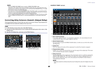
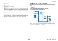
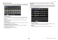
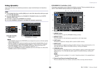
6 DELAY button Switches the output port delay on or off. 7 Ø (Phase) button Switches the phase of the signal assigned to the output port between normal phase (black) and reverse phase (yellow). 8 GAIN knob Adjusts the output gain of the output port. To adjust this value, press the knob on screen to select it, and then operate the [TOUCH AND TURN] knob. Rotate the knob to set the value in 1.0 dB steps. Rotate the knob while pressing and holding it down to set the value in 0.1 dB steps. The current value appears immediately below the knob. 9 Level meter Indicates the level of the signal assigned to the output port. 0 Tabs Switch the output ports controlled in groups of up to eight ports. Tabs are categorized into three groups: DANTE, SLOT, and PATCH VIEW. To display tabs in the desired group, press the group name button located at the right or left end of the bottom row. Using the PORT TO PORT function OUTPUT channels STEP 1. In the Function Access Area, press the SETUP button. 2. Press the OUTPUT PORT button in the SYSTEM SETUP field located in the center of the SETUP screen. 3. Press the channel select button in the OUTPUT PORT screen. 4. In the CH SELECT screen, select the output port. HA AD HA AD INPUT INPUT INPUT PATCH OUTPUT PATCH SLOT SLOT Dante OUTPUT OUTPUT DA DA SLOT SLOT Dante Use the PORT TO PORT function to output from an input jack on the rear panel to a Dante connector without sending the signal through the mixer. This allows you to use the I/O jacks on QL series consoles as I/O jacks for an audio network. 47 Reference Manual
-
 1
1 -
2
-
3
-
4
-
5
-
6
-
7
-
8
-
9
-
10
-
11
-
12
-
13
-
14
-
15
-
16
-
17
-
18
-
19
-
20
-
21
-
22
-
23
-
24
-
25
-
26
-
27
-
28
-
29
-
30
-
31
-
32
-
33
-
34
-
35
-
36
-
37
-
38
-
39
-
40
-
41
-
 42
42 -
 43
43 -
 44
44 -
 45
45 -
 46
46 -
 47
47 -
 48
48 -
 49
49 -
 50
50 -
 51
51 -
 52
52 -
53
-
54
-
55
-
56
-
57
-
58
-
59
-
60
-
61
-
62
-
63
-
64
-
65
-
66
-
67
-
68
-
69
-
70
-
71
-
72
-
73
-
74
-
75
-
76
-
77
-
78
-
79
-
80
-
81
-
82
-
83
-
84
-
85
-
86
-
87
-
88
-
89
-
90
-
91
-
92
-
93
-
94
-
95
-
96
-
97
-
98
-
99
-
100
-
101
-
102
-
103
-
104
-
105
-
106
-
107
-
108
-
109
-
110
-
111
-
112
-
113
-
114
-
115
-
116
-
117
-
118
-
119
-
120
-
121
-
122
-
123
-
124
-
125
-
126
-
127
-
128
-
129
-
130
-
131
-
132
-
133
-
134
-
135
-
136
-
137
-
138
-
139
-
140
-
141
-
142
-
143
-
144
-
145
-
146
-
147
-
148
-
149
-
150
-
151
-
152
-
153
-
154
-
155
-
156
-
157
-
158
-
159
-
160
-
161
-
162
-
163
-
164
-
165
-
166
-
167
-
168
-
169
-
170
-
171
-
172
-
173
-
174
-
175
-
176
-
177
-
178
-
179
-
180
-
181
-
182
-
183
-
184
-
185
-
186
-
187
-
188
-
189
-
190
-
191
-
192
-
193
-
194
-
195
-
196
-
197
-
198
-
199
-
200
-
201
-
202
-
203
-
204
-
205
-
206
-
207
-
208
-
209
-
210
-
211
-
212
-
213
-
214
-
215
-
216
-
217
-
218
-
219
-
220
-
221
-
222
-
223
-
224
-
225
-
226
-
227
-
228
-
229
-
230
-
231
-
232
-
233
-
234
-
235
-
236
-
237
-
238
-
239
-
240
-
241
-
242
-
243
-
244
-
245
-
246
-
247
-
248
-
249
-
250
-
251
-
252
-
253
-
254
-
255
-
256
-
257
-
258
-
259
-
260
-
261
-
262
-
263
-
264
 |
 |
