Yamaha QL5 Reference Manual - Page 26
Making HA (Head Amp) settings, Setting the gain
 |
View all Yamaha QL5 manuals
Add to My Manuals
Save this manual to your list of manuals |
Page 26 highlights
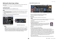
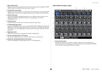
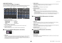
Making HA (Head Amp) settings You can make HA (Head Amp) related settings (phantom power on/off, gain, phase) for the input channel. • To adjust only the HA analog gain, use the [TOUCH AND TURN] knob. Setting the gain Head amp settings are made in the GAIN/PATCH window. STEP 1. Press the Bank Select keys in the Fader Bank section and the [SEL] keys on the top panel to select the channel. 2. Press the GAIN knob in the GAIN/PATCH field in the SELECTED CHANNEL VIEW screen. 3. Press the 1ch or 8ch tab in the GAIN/PATCH window. 4. Make settings for the head amp. SELECTED CHANNEL VIEW screen GAIN/PATCH window (1ch) NOTE • The PAD will be switched on or off internally when the HA gain is adjusted between +17 dB and +18 dB. • Keep in mind that noise may be generated when using phantom power if there is a difference between the Hot and Cold output impedance of an external device connected to the INPUT jack. • The GAIN knob, +48V button, and Ø button are valid only on channels for which the assigned input port is an INPUT jack on the I/O device, the INPUT jack on the QL unit, or a slot that is connected to an external head amp device (e.g., Yamaha AD8HR or SB168-ES). GAIN/PATCH window (1ch) 1 9 Input channels 0 2 3 4 5 6 78 1 Channel icon/Channel number/Channel name indicator Indicates the channel icon, number, and name. 2 HA section Appears if the head amp is patched to the input channel. NOTE • If a slot is patched to the channel, the type of the slot/MY card and the slot meter will be displayed. • If a rack is patched, the type of rack and type of effect will be displayed. • +48V button Switches head amp phantom power (+48V) on or off. • A.GAIN (analog gain) knob Indicates the analog gain of the head amp. You can use the [TOUCH AND TURN] knob to adjust the gain. If the Gain Compensation function is turned on, an indicator will appear, showing the position of the analog gain when the function is turned on. • HA meter Displays the level of the HA input signal. • GC (Gain Compensation) ON/OFF button Turns the Gain Compensation (gain correction function) on or off. If the Gain Compensation function is turned on, the level of the signal output from the I/O device to the audio network will be stabilized. For example, if the FOH console and the monitoring console are sharing an I/O device, or if you are performing digital recording via Dante connections, using this function will maintain the signal output at a constant level from the I/O device to the network even if the analog gain value on the I/O device is changed. If the Gain Compensation function is turned off, the analog gain and digital gain will return to the level that was obtained when you turned on the function. Therefore, the signal level on the digital network will remain the same. • Gain compensation meter Indicates the level of the signal output to the audio network after gain compensation. 26 Reference Manual
-
 1
1 -
2
-
3
-
4
-
5
-
6
-
7
-
8
-
9
-
10
-
11
-
12
-
13
-
14
-
15
-
16
-
17
-
18
-
19
-
20
-
 21
21 -
 22
22 -
 23
23 -
 24
24 -
 25
25 -
 26
26 -
 27
27 -
 28
28 -
 29
29 -
 30
30 -
 31
31 -
32
-
33
-
34
-
35
-
36
-
37
-
38
-
39
-
40
-
41
-
42
-
43
-
44
-
45
-
46
-
47
-
48
-
49
-
50
-
51
-
52
-
53
-
54
-
55
-
56
-
57
-
58
-
59
-
60
-
61
-
62
-
63
-
64
-
65
-
66
-
67
-
68
-
69
-
70
-
71
-
72
-
73
-
74
-
75
-
76
-
77
-
78
-
79
-
80
-
81
-
82
-
83
-
84
-
85
-
86
-
87
-
88
-
89
-
90
-
91
-
92
-
93
-
94
-
95
-
96
-
97
-
98
-
99
-
100
-
101
-
102
-
103
-
104
-
105
-
106
-
107
-
108
-
109
-
110
-
111
-
112
-
113
-
114
-
115
-
116
-
117
-
118
-
119
-
120
-
121
-
122
-
123
-
124
-
125
-
126
-
127
-
128
-
129
-
130
-
131
-
132
-
133
-
134
-
135
-
136
-
137
-
138
-
139
-
140
-
141
-
142
-
143
-
144
-
145
-
146
-
147
-
148
-
149
-
150
-
151
-
152
-
153
-
154
-
155
-
156
-
157
-
158
-
159
-
160
-
161
-
162
-
163
-
164
-
165
-
166
-
167
-
168
-
169
-
170
-
171
-
172
-
173
-
174
-
175
-
176
-
177
-
178
-
179
-
180
-
181
-
182
-
183
-
184
-
185
-
186
-
187
-
188
-
189
-
190
-
191
-
192
-
193
-
194
-
195
-
196
-
197
-
198
-
199
-
200
-
201
-
202
-
203
-
204
-
205
-
206
-
207
-
208
-
209
-
210
-
211
-
212
-
213
-
214
-
215
-
216
-
217
-
218
-
219
-
220
-
221
-
222
-
223
-
224
-
225
-
226
-
227
-
228
-
229
-
230
-
231
-
232
-
233
-
234
-
235
-
236
-
237
-
238
-
239
-
240
-
241
-
242
-
243
-
244
-
245
-
246
-
247
-
248
-
249
-
250
-
251
-
252
-
253
-
254
-
255
-
256
-
257
-
258
-
259
-
260
-
261
-
262
-
263
-
264
 |
 |
