ZyXEL ENC User Guide - Page 235
The AP Monitor Screen, 8.6 IP Surveillance
 |
View all ZyXEL ENC manuals
Add to My Manuals
Save this manual to your list of manuals |
Page 235 highlights
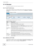
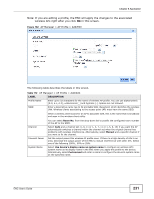
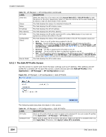
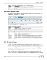
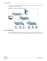
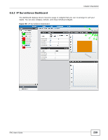
Chapter 8 Application Table 114 AP Manager > AP Configuration > Edit AP Profile (continued) LABEL DESCRIPTION Cancel Click Cancel to close this screen without saving the settings. Ok Click Ok to save the settings. 8.5.4 The AP Monitor Screen Use this screen to view the current status of all managed wireless APs. To open this screen, click Application > AP Manager > AP Monitor. Figure 185 AP Manager > AP Monitor The following table describes the labels in this screen. Table 115 AP Manager > AP Monitor LABEL DESCRIPTION Status This field displays the current status of a wireless AP. Name This field displays the name of the AP. MAC Address This field displays the MAC address of the AP. IP Address This field displays the IP address of the AP. TX This field displays the data transmitting rate of the AP. RX This field displays the data receiving rate of the AP. Number of Retries This field displays the number of times the AP retransmited packets to its clients due to interferences occurred on the wireless channel since the AP was last time restarted. Associated Stations This field displays the number of wireless clients which are currently wirelessly associated with the AP. 8.6 IP Surveillance The ENC can manage IP Surveillance cameras connected to switches. Using the ENC you can remotely manage power and traffic usage for each switch port that a camera is connected to. In the network, IP Surveillance cameras are connected to an Access Switch. Access Switches are then connected to an Aggregate Switch. The connection between the Access Switch and Aggregate Switch is called a Trunk, and the port on which this traffic is transmitted is called an Uplink port. The Aggregate Switch is connected to the Network Video Recorder (NVR) Switch. An NVR server and the ENC are connected to the NVR Switch. In the figure below, the IP cameras are connected to Access Switches S3 and S4. The Access Switches are connected to Aggregate Switch S2, which is connected to the NVR Switch S1. The NVR ENC User's Guide 235
-
 1
1 -
2
-
3
-
4
-
5
-
6
-
7
-
8
-
9
-
10
-
11
-
12
-
13
-
14
-
15
-
16
-
17
-
18
-
19
-
20
-
21
-
22
-
23
-
24
-
25
-
26
-
27
-
28
-
29
-
30
-
31
-
32
-
33
-
34
-
35
-
36
-
37
-
38
-
39
-
40
-
41
-
42
-
43
-
44
-
45
-
46
-
47
-
48
-
49
-
50
-
51
-
52
-
53
-
54
-
55
-
56
-
57
-
58
-
59
-
60
-
61
-
62
-
63
-
64
-
65
-
66
-
67
-
68
-
69
-
70
-
71
-
72
-
73
-
74
-
75
-
76
-
77
-
78
-
79
-
80
-
81
-
82
-
83
-
84
-
85
-
86
-
87
-
88
-
89
-
90
-
91
-
92
-
93
-
94
-
95
-
96
-
97
-
98
-
99
-
100
-
101
-
102
-
103
-
104
-
105
-
106
-
107
-
108
-
109
-
110
-
111
-
112
-
113
-
114
-
115
-
116
-
117
-
118
-
119
-
120
-
121
-
122
-
123
-
124
-
125
-
126
-
127
-
128
-
129
-
130
-
131
-
132
-
133
-
134
-
135
-
136
-
137
-
138
-
139
-
140
-
141
-
142
-
143
-
144
-
145
-
146
-
147
-
148
-
149
-
150
-
151
-
152
-
153
-
154
-
155
-
156
-
157
-
158
-
159
-
160
-
161
-
162
-
163
-
164
-
165
-
166
-
167
-
168
-
169
-
170
-
171
-
172
-
173
-
174
-
175
-
176
-
177
-
178
-
179
-
180
-
181
-
182
-
183
-
184
-
185
-
186
-
187
-
188
-
189
-
190
-
191
-
192
-
193
-
194
-
195
-
196
-
197
-
198
-
199
-
200
-
201
-
202
-
203
-
204
-
205
-
206
-
207
-
208
-
209
-
210
-
211
-
212
-
213
-
214
-
215
-
216
-
217
-
218
-
219
-
220
-
221
-
222
-
223
-
224
-
225
-
226
-
227
-
228
-
229
-
 230
230 -
 231
231 -
 232
232 -
 233
233 -
 234
234 -
 235
235 -
 236
236 -
 237
237 -
 238
238 -
 239
239 -
 240
240 -
241
-
242
-
243
-
244
-
245
-
246
-
247
-
248
-
249
-
250
-
251
-
252
-
253
-
254
-
255
-
256
-
257
-
258
-
259
-
260
-
261
-
262
-
263
-
264
-
265
-
266
-
267
-
268
-
269
-
270
-
271
-
272
-
273
-
274
-
275
-
276
-
277
-
278
-
279
-
280
-
281
-
282
-
283
-
284
-
285
-
286
-
287
-
288
-
289
-
290
-
291
-
292
-
293
-
294
-
295
-
296
-
297
-
298
-
299
-
300
-
301
-
302
-
303
-
304
-
305
-
306
-
307
-
308
-
309
-
310
-
311
-
312
-
313
-
314
-
315
-
316
-
317
-
318
-
319
-
320
-
321
-
322
-
323
-
324
-
325
-
326
-
327
-
328
-
329
-
330
-
331
-
332
-
333
-
334
-
335
-
336
-
337
-
338
-
339
-
340
-
341
-
342
-
343
-
344
-
345
-
346
-
347
-
348
-
349
-
350
-
351
-
352
-
353
-
354
-
355
-
356
-
357
-
358
-
359
-
360
-
361
-
362
-
363
-
364
-
365
-
366
-
367
-
368
-
369
-
370
-
371
-
372
-
373
-
374
-
375
-
376
-
377
-
378
-
379
-
380
-
381
-
382
-
383
-
384
-
385
-
386
-
387
-
388
-
389
-
390
 |
 |