ZyXEL ENC User Guide - Page 34
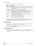
Main Window, 1.3.5 Right-click Menus, Table 9, LABEL, DESCRIPTION
 |
View all ZyXEL ENC manuals
Add to My Manuals
Save this manual to your list of manuals |
Page 34 highlights
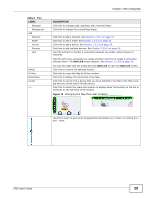
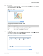
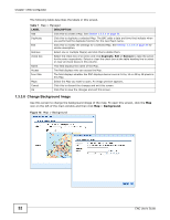
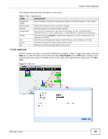
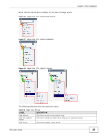
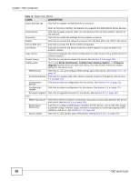
Chapter 1 Web Configurator The following table describes the labels in the Add Link screen. Table 9 Map > Add Link LABEL DESCRIPTION Link Label (Name) Enter up to 32 characters for the link's name for identification purposes. You can use alphanumeric characters (0-9, a-z, A-Z), arrow brackets (), underscores (_), hyphen (-), dot (.) and spaces. Link Endpoint 1 This field displays the first node's IP address that you selected. Link Endpoint 2 This field displays the second node's IP address that you selected. Interface Index Enter the index number of a port or an interface on the device you specified in the Associated IP field. The ENC will monitor it to check the connectivity. Refer to the device's User's Guide for the number of the port or interface you should enter. Associated IP Enter the IP address of the endpoint 1 or 2 device. The ENC will use it to check and determine whether this link is up or down. Link Type Select the type and the maximum transmission speed of this link. If you are not clear about the settings, leave them to the defaults. Description Type additional information for this link in this field. Cancel Click this to discard the changes and exit this screen. Ok Click this to save the changes and exit this screen. After you configure the link settings completely, a line displays between two nodes. The link becomes gray when the ENC is trying to send poll messages to the device. It is green when the connection between two nodes is up or red when they are disconnected. 1.3.4 Main Window The main window shows the screen you select in the navigation panel (D in Figure 6 on page 25). The main window screens are discussed in the rest of this document. Right after you log in, the Dashboard screen is displayed. See Chapter 3 on page 85 for more information about the Dashboard screen. 1.3.5 Right-click Menus In the OTV panel, right-click the Root Subnet network, a network under Root Subnet or a device, different menus display respectively. These menus provide a shortcut to execute a function for the network or device. 34 ENC User's Guide
-
 1
1 -
2
-
3
-
4
-
5
-
6
-
7
-
8
-
9
-
10
-
11
-
12
-
13
-
14
-
15
-
16
-
17
-
18
-
19
-
20
-
21
-
22
-
23
-
24
-
25
-
26
-
27
-
28
-
 29
29 -
 30
30 -
 31
31 -
 32
32 -
 33
33 -
 34
34 -
 35
35 -
 36
36 -
 37
37 -
 38
38 -
 39
39 -
40
-
41
-
42
-
43
-
44
-
45
-
46
-
47
-
48
-
49
-
50
-
51
-
52
-
53
-
54
-
55
-
56
-
57
-
58
-
59
-
60
-
61
-
62
-
63
-
64
-
65
-
66
-
67
-
68
-
69
-
70
-
71
-
72
-
73
-
74
-
75
-
76
-
77
-
78
-
79
-
80
-
81
-
82
-
83
-
84
-
85
-
86
-
87
-
88
-
89
-
90
-
91
-
92
-
93
-
94
-
95
-
96
-
97
-
98
-
99
-
100
-
101
-
102
-
103
-
104
-
105
-
106
-
107
-
108
-
109
-
110
-
111
-
112
-
113
-
114
-
115
-
116
-
117
-
118
-
119
-
120
-
121
-
122
-
123
-
124
-
125
-
126
-
127
-
128
-
129
-
130
-
131
-
132
-
133
-
134
-
135
-
136
-
137
-
138
-
139
-
140
-
141
-
142
-
143
-
144
-
145
-
146
-
147
-
148
-
149
-
150
-
151
-
152
-
153
-
154
-
155
-
156
-
157
-
158
-
159
-
160
-
161
-
162
-
163
-
164
-
165
-
166
-
167
-
168
-
169
-
170
-
171
-
172
-
173
-
174
-
175
-
176
-
177
-
178
-
179
-
180
-
181
-
182
-
183
-
184
-
185
-
186
-
187
-
188
-
189
-
190
-
191
-
192
-
193
-
194
-
195
-
196
-
197
-
198
-
199
-
200
-
201
-
202
-
203
-
204
-
205
-
206
-
207
-
208
-
209
-
210
-
211
-
212
-
213
-
214
-
215
-
216
-
217
-
218
-
219
-
220
-
221
-
222
-
223
-
224
-
225
-
226
-
227
-
228
-
229
-
230
-
231
-
232
-
233
-
234
-
235
-
236
-
237
-
238
-
239
-
240
-
241
-
242
-
243
-
244
-
245
-
246
-
247
-
248
-
249
-
250
-
251
-
252
-
253
-
254
-
255
-
256
-
257
-
258
-
259
-
260
-
261
-
262
-
263
-
264
-
265
-
266
-
267
-
268
-
269
-
270
-
271
-
272
-
273
-
274
-
275
-
276
-
277
-
278
-
279
-
280
-
281
-
282
-
283
-
284
-
285
-
286
-
287
-
288
-
289
-
290
-
291
-
292
-
293
-
294
-
295
-
296
-
297
-
298
-
299
-
300
-
301
-
302
-
303
-
304
-
305
-
306
-
307
-
308
-
309
-
310
-
311
-
312
-
313
-
314
-
315
-
316
-
317
-
318
-
319
-
320
-
321
-
322
-
323
-
324
-
325
-
326
-
327
-
328
-
329
-
330
-
331
-
332
-
333
-
334
-
335
-
336
-
337
-
338
-
339
-
340
-
341
-
342
-
343
-
344
-
345
-
346
-
347
-
348
-
349
-
350
-
351
-
352
-
353
-
354
-
355
-
356
-
357
-
358
-
359
-
360
-
361
-
362
-
363
-
364
-
365
-
366
-
367
-
368
-
369
-
370
-
371
-
372
-
373
-
374
-
375
-
376
-
377
-
378
-
379
-
380
-
381
-
382
-
383
-
384
-
385
-
386
-
387
-
388
-
389
-
390
 |
 |